Multilevel inverters (MLI) plays vital role in the field of power electronics and being widely used in many industrial and commercial applications since it possess low electromagnetic interference and the efficiency is considerably high. Neutral point clamped, flying capacitor and cascaded H bridge multilevel inverter are the basic multilevel inverter topologies available. Even though the multilevel inverter plays a vital role, usage of more switches in the conventional configuration poses a limitation to its wide range application. The number of switching devices in the converter system can be reduced by adopting hybrid topology. The topology used here is a three phase seven level hybrid inverter consisting of three level cascaded H- Bridge (CHBMLI) and neutral point clamped multilevel inverter (NPCMLI). Asymmetric dc bus voltage ratio is employed to increase the number of levels of the entire system. The number of levels in line voltage could be increased to 13 levels by third harmonic injection. The main objective of this hybridised structure is to reduce the number of switches with the increase in number of levels. The performance of this hybrid structure with and without third harmonic injection is analyzed in this paper by simulation in MATLAB/SIMULINK. A prototype of single phase topology is also developed.
Keywords |
| Multilevel Inverter, NPC-HB topology, hybrid, asymmetrical, third harmonic injection |
INTRODUCTION |
| Power electronic converters have gained great interest for various industrial applications. Series and parallel connection
of switches is adopted as an effective solution to face the limitation of semiconductors current and voltage ratings for
high power applications. The output of inverter with stepped waveform has better harmonic spectrum than 2-level
waveform in low switching frequencies [1]. Hence, recently multilevel inverters are widely accepted in industry.
Different topologies are available which allow us to generate more voltage levels with reduction in number of
semiconductors and to increase the output performance and system reliability. In this condition, hybrid topology has
attracted a lot of attention both from the customers and from the manufacturers. The topology used in this paper,
consists of diode clamped and cascaded H bridge multilevel inverter. Based on this topology, the number of levels
could be increased with less number of switches. |
MULTILEVEL INVERTER |
| In multilevel inverters, semiconductors and dc voltage sources are arranged so as to generate a staircase output voltage
waveform. Multilevel power conversion came into effect 20 years ago which allows converter operating voltage to be
increased beyond the limits of classical semiconductors. Multilevel Inverter is an arrangement of power
semiconductors and capacitors so as to obtain high-quality load voltage generation. Higher number of semiconductor
switches is utilised to perform power conversion in small voltage steps. Multilevel power converters can be considered
as voltage synthesizers in which output high voltage is generated from many discrete smaller levels of voltage. The
multilevel topologies can be classified into three main categories: the diode clamped, the flying capacitors (FC) and the
cascade H-bridge (CHB) converters [2]. With the increase in number of levels with small voltage steps we could obtain
the waveforms with high power quality and low electromagnetic interference[3]. |
SIGNIFICANCE OF HYBRID TOPOLOGY |
| Hybrid topologies are the new multilevel inverter topologies proposed based on the existing topologies so as to
achieve some improvements for medium voltage and high power industrial drives. They are widely promoted because the harmonic contents of output voltage can be reduced without increasing the number of power devices. The power
processing of the entire system is optimised by the use of various DC voltages sources for the hybrid multilevel
inverters. |
| On comparison with a symmetric multilevel inverter, we could obtain different output voltage levels by the addition
and subtraction of voltages, with the same number of components. The requirement of output filters can be eliminated
[4]. Each power module of this hybrid structure can be operated at a specific DC voltage and switching frequency, so as
to achieve the efficiency enhancement and THD compensation characteristics of inverter. For diode clamped and
flying capacitor, there is no limitation for the number of levels whereas the cascade H-bridge can possess only odd
number of levels; where two levels adds up with the first cell which gives three levels with the addition of each H
bridge [5]. |
NPC-H BRIDGE HYBRID TOPOLOGY |
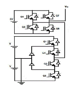
| The topology discussed in this paper is a hybrid between the three level NPC and three level H-bridge cells
connected in series. The basic circuit diagram for this topology is as shown in fig. 1. Asymmetric (binary) dc bus
voltage ratio is used to increase the number of levels [6]. We could optimise the switching losses by this asymmetric
ratio. The source voltage which is applied to NPC structure is doubled and is given to the H bridge. HBMLI and
DCMLI topologies are hybridized to improve power distribution ratio of cells which results in reduction of
semiconductor devices [7]. |
SWITCHING STATES AND CONTROL SIGNAL |
| The different switching states of NPC-H bridge topology and the total hybrid converter output voltage that can be
generated as different levels is given in table. I. The switching table here indicates the switching sequence for a single
phase for the topology shown in fig.1 so as to obtain 3V to -3V. Q1, Q2, Q3 and Q4 are respective switches of NPC
structure and Q5, Q6, Q7 and Q8 are that of cascaded H bridge where four of them are compliment of other. The
voltage from the NPC structure will be added up with H bridge to achieve higher number of levels. The switching
pulses are generated using the Carrier based Sinusoidal Pulse width modulation. |
| According to carrier based PWM, to obtain n number of levels, (n-1) number of carriers is required. In this topology,
the voltage levels obtained in line to neutral are 7. Hence, six triangular carrier waves are required with the reference
sine wave. |
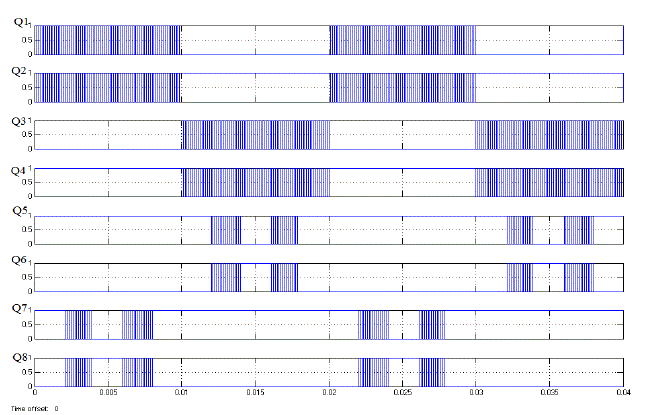
| Different types of carrier based PWM schemes are available and here Phase Disposition method is adopted. The
control pulses generated for the eight switches are according to this control logic. In the Phase disposition (PD) method
used here, all carrier waveforms are in phase. The control pulses generated for this topology is as shown in fig. 2. |
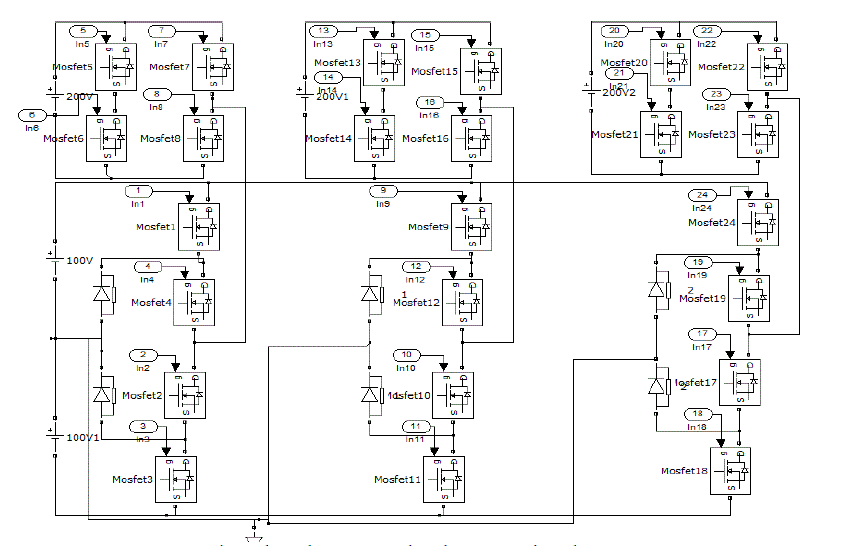
| The three phase structure based on proposed hybrid topology to which these control pulses are applied is shown in
fig. 3.The control pulses for the eight switches in phase A is applied respectively to phase B and C with a phase shift of
120 degree to the corresponding gate terminal. |
THIRD HARMONIC INJECTION |
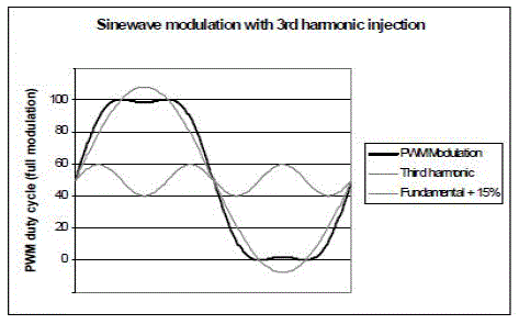
| Third harmonic voltage injection in phase voltage enable increase in the number of levels in line voltage by about
15% . The third harmonic voltage waveform can be generated by modifying the modulating waveform by the addition
of one sixth of third harmonics to this waveform. This cause the reduction in the peak value of output waveform by a
factor of 0.866 without changing the amplitude of fundamental [8]. This third harmonic generation is shown in Fig.4. |
| The line voltage levels will be (2N+2-3) after third harmonic injection, while it is √3*(2N-1)*2+1 without third
harmonic injection. Hence, for this inverter the number of voltage levels is 7 in phase to neutral and 11 as number of
levels in line to line voltage .By third harmonic injection, this line to line voltage can be increased to 13. |
SIMULATION STUDIES |
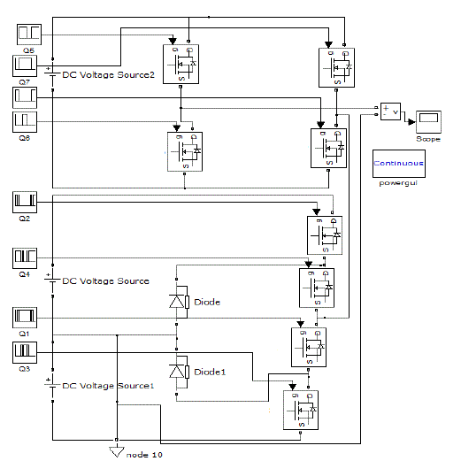
| The simulation is carried out using MATLAB/SIMULINK to evaluate the proposed hybrid topology and its control
method. 100V and 200V source voltage is given respectively to the Neutral point clamped structure and the Cascaded
H bridge respectively. The simulation model to test the operation of seven level inverter in single phase is as shown in
fig. 5. |
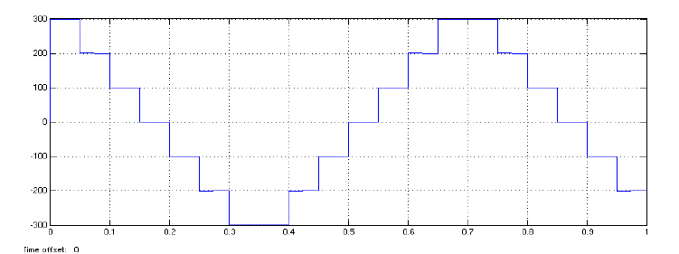
| The test result of seven level inverter MATLAB/SIMULINK is shown in fig. 6 with voltage levels between -300 V
to 300 V. |
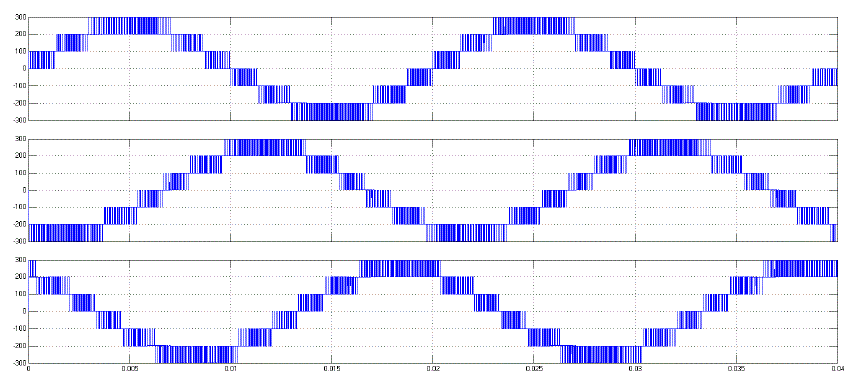
| The seven level output obtained in three phases after the control pulses are given is as shown in fig. 7. |
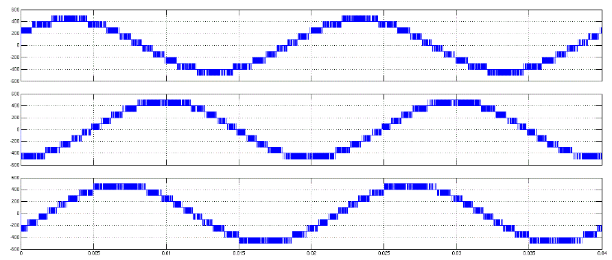
| The line voltage obtained without third harmonic injection for the three phases is as shown in fig. 8. The voltage
level of line voltage varies between +500 to -500 V, so that 11 levels of output voltage is obtained. |
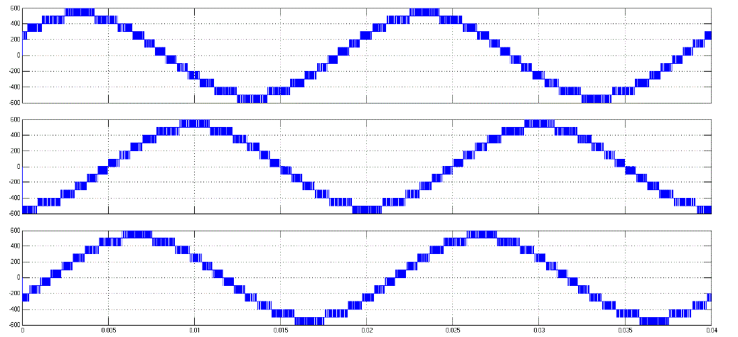
| When third harmonic voltage is injected, the number of levels in line voltage can be improved as shown in fig. 9.
Here, after the third harmonic injection the line to line voltage is in the range of +600 to -600V, so that the number of
levels is increased to 13. |
FFT ANALYSIS |
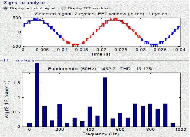
| The spectral analysis of the MATLAB/SIMULINK model of NPC-H bridge hybrid topology is performed. The FFT
analysis for the output signal is performed at a fundamental frequency of 50 Hz and the THD analysis for line to line
voltage without third harmonic injection is shown in fig. 10. |
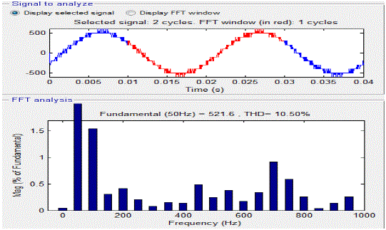
| Similarly, the THD analysis result obtained for line voltage after the injection of third harmonic voltage is as shown
in fig. 11 and the reduction in total harmonic distortion is observed. Also the higher order harmonics are suppressed
using this method. |
HARDWARE SETUP |
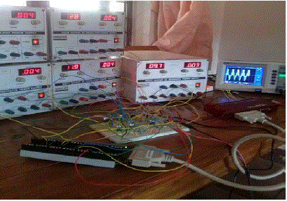
| The hardware structure set up is shown in fig. 12 below. Since asymmetric binary ratio is adopted, the source
voltage supplied was 5 V and 10 V respectively for the NPC and cascaded H bridge topology. The hardware is setup
using the DAQ interfacing system for the control pulses. MOSFET switches IRF540 and optocoupler MCT2E is used
for isolation. |
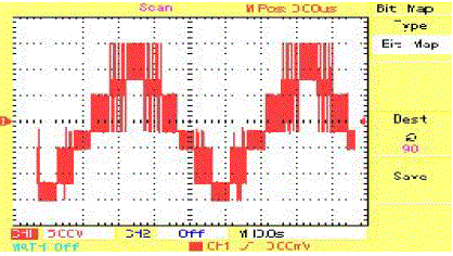
| The output was observed in DSO as seven levels obtained between -15 V to 15V after control pulses are given to
the gate terminal of MOSFET and is shown in fig. 13. |
CONCLUSION |
| Asymmetric hybrid multilevel inverter is developed. It combines the advantages of three level Neutral point clamped
inverter and H bridge. Seven level output is obtained based on the simulation carried out on this hybrid topology in
each phase. The Total Harmonic Distortion for the phase voltage is obtained as about 23%. Through this topology, we
could reduce the number of switches and hence the switching losses for increased number of levels. Total Harmonic
Distortion could be reduced with increase in number of levels. The number of levels could be improved by 15% using
third harmonic injection, so that THD in line voltage is reduced to 10.5% from 13.2%. All the other dominating
harmonic components in line to line voltage could be reduced by the third harmonic injection. Also the number of
levels are increased from 11 to 13 in three phase line voltage. The hardware for the single phase of this topology is set
up using MOSFET switches and the control pulses are given through DAQ and the seven level output is obtained. |
Tables at a glance |
 |
| Table 1 |
|
Figures at a glance |
 |
 |
 |
 |
 |
| Figure 1 |
Figure 2 |
Figure 3 |
Figure 4 |
Figure 5 |
 |
 |
 |
 |
 |
| Figure 6 |
Figure 7 |
Figure 8 |
Figure 9 |
Figure 10 |
 |
 |
 |
| Figure 11 |
Figure 12 |
Figure 13 |
|
References |
- Alipio BC, David FC, Isabel RS, Juan CNM. Manuel AE. Comparison of batch, stirred flow chamber, and column experiments to study adsorption, Desorption and transport of carbofuran within two acidic soils. Chemosphere. 2012; 88(1): 106-120.
- Arnaud B, Richard C, Michel S. A comparison of five pesticides adsorption and Desorption processes in thirteen contrasting field soils. Chemosphere. 2005; 61(5): 668-676.
- Chunxian W, Jin-Jun W, Su-Zhi Z, Zhong-Ming Z. Adsorption and Desorption of Methiopyrsulfuron in Soils. Pedosphere. 2011; 21(3): 380-388.
- Chunxian W, Suzhi Z, Guo N, Zhongming Z, Jinjun W. Adsorption and Desorption of herbicide monosulfuron-ester in Chinese soils. J Environ Sci. 2011; 23(9): 1524-1532.
- Christine MFB, Josette MF. Adsorption-desorption and leaching of phenylurea herbicides on soils. Talanta. 1996; 43(10): 1793-1802.
|