Keywords
|
| Modular converter, continuous and discontinuous pulse width modulations (PWM) Techniques. |
INTRODUCTION
|
The progress of high-power high-voltage power electronic equipment for various medium- to high-voltage applications Continues to benefit from the advancement of the high-powerFully-controlled semiconductors [1]. Applications for such Equipment include motor drives, traction systems [1], high Voltage direct current (HVDC) power transmission [2], flexible alternating current transmission systems (FACTS) such as static compensators (STATCOMs) to mention just few [3]. As the level of power and voltage needs to be increased for many applications, the rapid development of multilevel voltage source converters (VSCs) over the last three decades has resulted, for instance, in many successful commercially viable HVDC systems [2]. In multilevel converters, the staircase Approximation of the sinusoidal waveform with numerous DC Sources is used, effectively reducing the total harmonic Distortion (THD) of the output voltage [1-2].The MMC [11-14] interesting multilevel converter providing various advantages, such as modular construction, multilevel waveform with a large number of steps and fault management [12]. An MMC can be configured using half- or full-bridge. circuits and their associated capacitors. The use of a number of full-bridge Submodules cascaded to create phase-legs result in an AC/ACConverter [13]. Similarly the uses of half-bridge submodules, or DC-choppers, cascaded in phase-legs are a DC/AC converter. The latter converter topology can also operate in a back-to back configuration for HVDC power transmission or motor Control, without the need of a large DC-side capacitor. This reduces the cost of the converter andincreases its reliability. However, limited information is available in the open technical literature about the performance of many well-knownPWM techniques [8] tocontrol the converter operation. Moreover, it is important to report the effects of the control method to a number of variables such as: the synthesis of the voltage waveform, the charging and discharging of the floating capacitors, the total harmonic distortion and associated switching losses 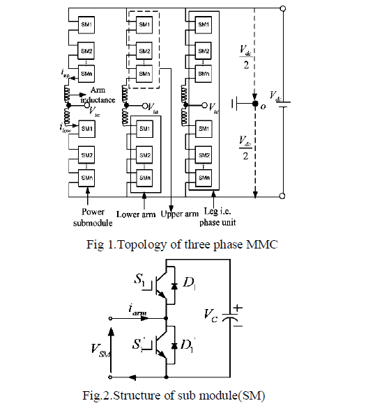 |
| The objective of this paper is to contribute to the Understanding of the operation and performance of the MMC Topology under Continuous and Discontinuous PWM techniques. PWM applies a pulse train of fixed amplitude and frequency only the width is varied in proportion to an input voltage In PWM technique the power semiconductor switches are turned ON and turn OFF several times during HALF cycles and output voltage is controlled by changing the width pulse. |
LITERATURE SURVEY
|
| The idea behind doing this project is taken from different research papers presented in various conferences and IEEE transactions. I had gone through a number of research papers to obtain the basic knowledge about this research. I have taken different innovative idea from all these sources and I have applied those in research paper. |
| The multilevel inverters have drawn tremendous interest in the power industry. Modular structured multilevel inverter is very attractive in high voltage and high power application. It mayeasier to produce a high voltage, high power inverter with the multilevel structure because of the way in which device voltage stresses are controlled in thestructure [1]. By using multilevel structure, the stress on each switching device can be reduced proportional to the number of levels of the multilevel inverter. Thus, the inverter can handle higher voltage without using an expensive and bulky step-up transformer in various applications. As the number of inverter output voltage levels is increased, harmonics content of the output voltage waveform decreases significantly enough to avoid the need of bulky filters [7,9,10]. The multilevel inverter has drawn tremendous interest in the power industry. This inverter is very attractive in high-voltage and high-power applications. This inverter has a few advantages [16]. It may easier to produce a high-power and highvoltage inverter with the multilevel structure because of the way in which device voltage stresses are controlled in the structure. Increasing the number of voltage levels in the inverter without requiring higher ratings on individual devices can increase the power rating [11-13]. |
| The stress on each switching device can be reduced proportional to the number of levels of the multilevel inverter, thus the inverter can handle higher voltage without using an expensive and bulky step-up transformer in various application. As the number of voltage levels increases, the harmonic content of the output voltage waveform decreases significantly enough to avoid the need of bulky filters [2,6]. The topological structure of multilevel inverter must have less switching devices as far as possible, be capable of withstanding very high input voltage for high-power application and have lower switching frequency for each switching device [16]. |
MODULAR MULTILEVEL CONVERTERS
|
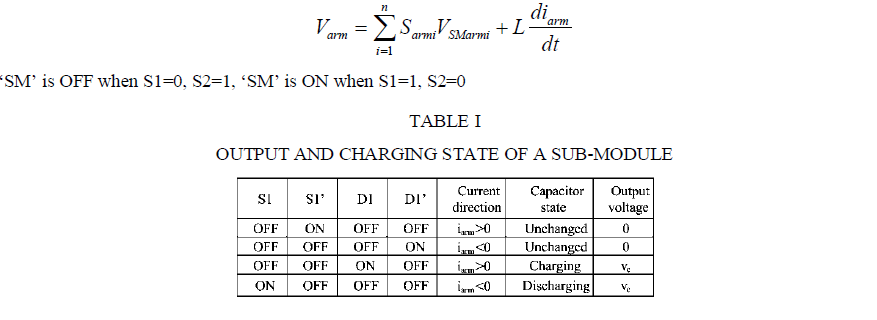
| Fig.1 shows the three-phase MMC with n sub-module in each arm. There are two arms in each phase, which are positive-arm and negative arm. The no. of levels in the output of the phase – leg depends not only on the no. of submodules in the arm of the topology but also on the way the converter leg depends not only on the no. of sub-modules in the arm of the topology but also on the way the converter leg is modulated. Output line-to-neutral voltage has n+1 levels if topology consisting of ‘n’ sub-modules per arm (2n per phase leg). The no. of sub-modules that are continuously connected in the whole phase leg remains constant and equal to n, meaning that n-upper + n-lower = n(where n-upper and n-lower are the sub-modules connected in the upper and lower arm respectively). When carrier phase-shifted SPWM is adopted, 2n sub-modules in each phase leg have 2n triangular waveforms with the same frequency but a phase difference of 3600/2n, thus output line-to-neutral voltage has 2n+1 levels. Fig. 2 is a single SM structure. The SM output voltage VSM has two values; VSM = VC, when the upper switch is on and the lower one is off; or VSM = 0 when the lower switch is on and the upper switch is off. This means each SM has only two states in normal operations: switched on or switched off. Output voltage and the states of charge on DC–side capacitor are listed in table 1. |
| Each of the arms of the topology can be seen as a voltage source, and the voltage of the arm is given by eq. [16]. |
 |
MULTICARRIER CONTINEOUS AND DISCONTINEOUS PWM TECHNIQUES
|
| PWM applies a pulse train of fixed amplitude and frequency only the width is varied in proportion to an input voltage In PWM technique the power semiconductor switches are turned ON and turn OFF several times during HALF cycles and output voltage is controlled by changing the width pulse N= number of carriers (n-1), Modulation index=Am/N’Ac Where N= (n-1)/2, Where n= number of levels Frequency of reference wave is 5o Hz and frequency of carrier is 2khz.We made comparing of reference wave and carrier wave its result is pure PWM for switching of switches for 3 level no. carriers requires two and for 5 level no. of carrier requires 4 upper two and lowers two. By using this technique we are giving the switching pulse to switches. The multicarrier PWM techniques are based on a single Modulating or reference signal, which in most cases is Sinusoidal. This reference waveform is compared and sampled through a number of triangular waveforms and for this reason the PWM techniques considered here are called multicarrier PWM techniques. They can be categorized as follows: |
| A. Phase disposition (PD) [7] |
| In the phase-disposition method all triangular carriers are in Phase the significant line-to-line voltage harmonics are presented as sidebands around the carrier frequency as the theory suggests. |
| B. Phase opposition disposition (POD) [7] |
| In POD, the positive and negative carriers are in phase, but between them, there is a phase shift of 180 degrees as shown in Fig. 4(b). Significant harmonics are presented, similarly to PD, as sidebands around the carrier frequency. |
| C. Alternative phase opposition disposition (APOD) [7] |
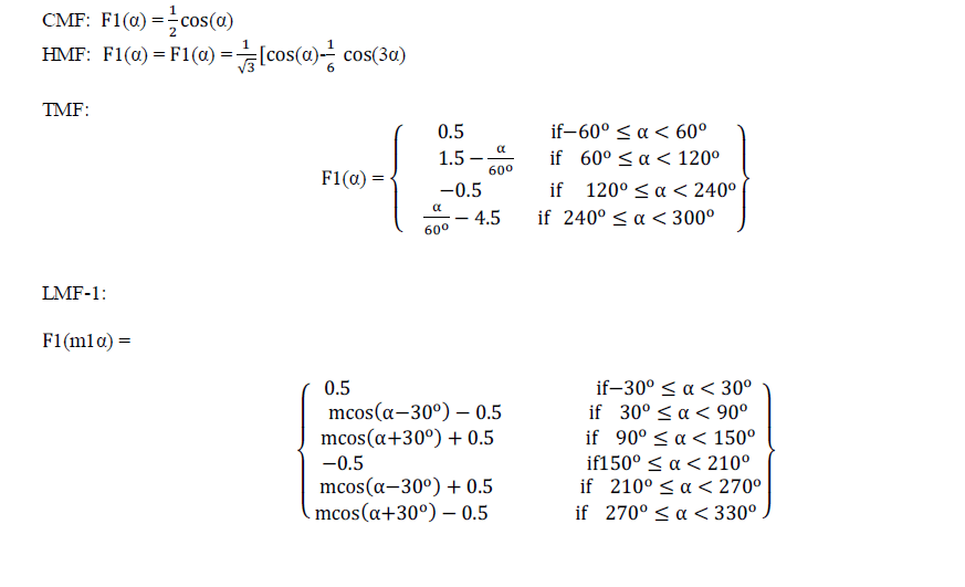
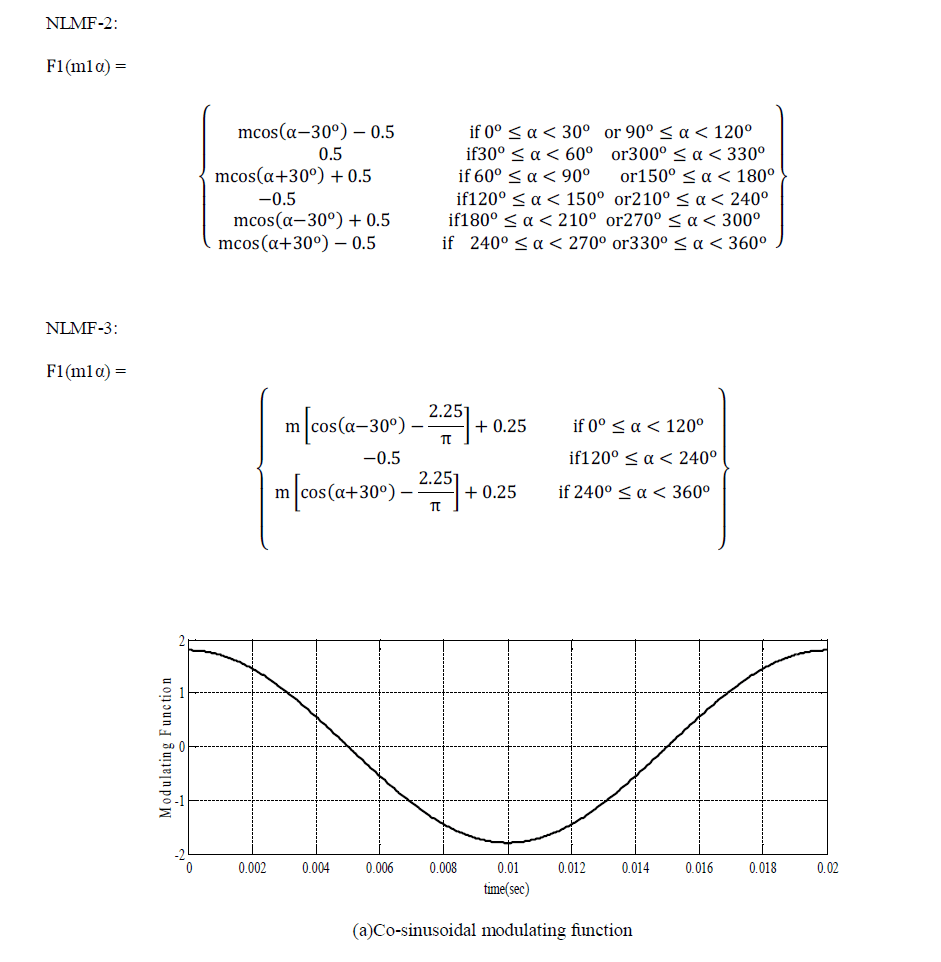
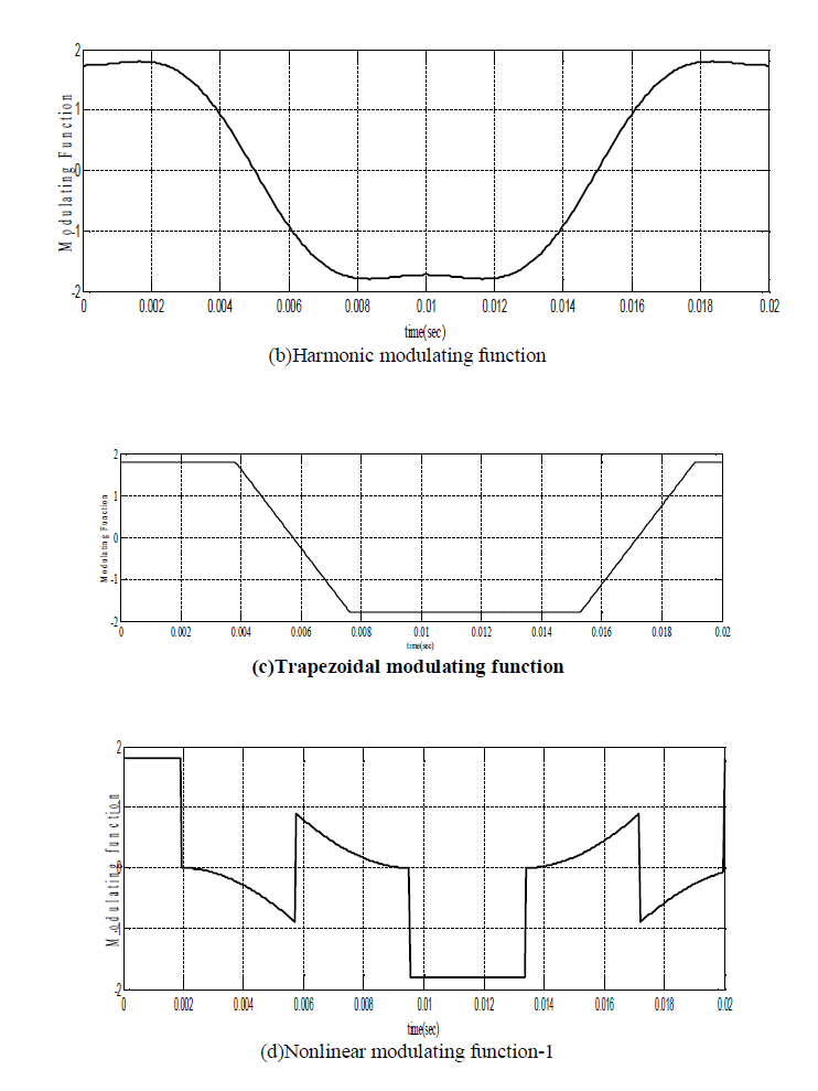
| In APOD, carrier signals are alternately displaced 180Degrees between them as shown in Fig.4(c). Similarly to the Previous two carrier disposition methods, sidebands to theCarrier frequency is presented as the most significant harmonics.The PD, POD and APOD control methods have theProperty of producing signals with significantly lower Switching frequency than the carrier frequency. The linear or continuous modulating functions are cosinusoidalmodulating functions (CMF), Harmonics modulating function (HMF), and Trapezoidal modulating function (TMF) and non-linear or discontinuous modulating functions are Non-linear modulating function NLMF-1, NLMF-2, NLMF-3. [15] |
 |
 |
 |
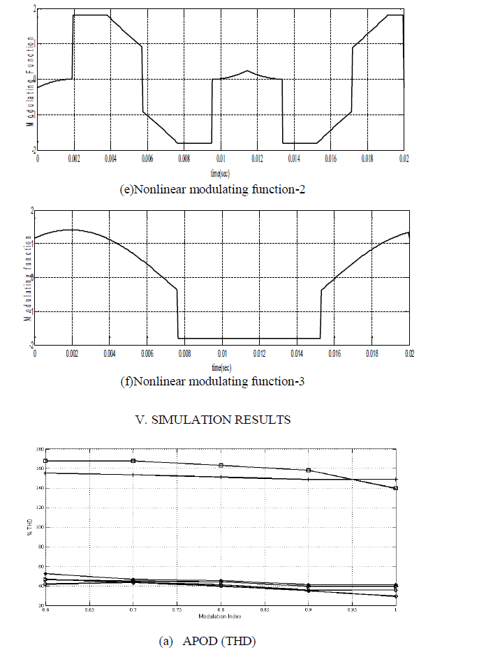 |
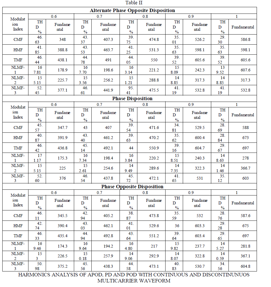
| The above results shows the percentage of THD of MMC verses different modulation index for different continuous and discontinues waveforms and Alternate Phase opposite disposition carrier waveform, where all carriers are alternatively in opposition, each carriers is phase shifted by 1800 from its adjacent carrier. |
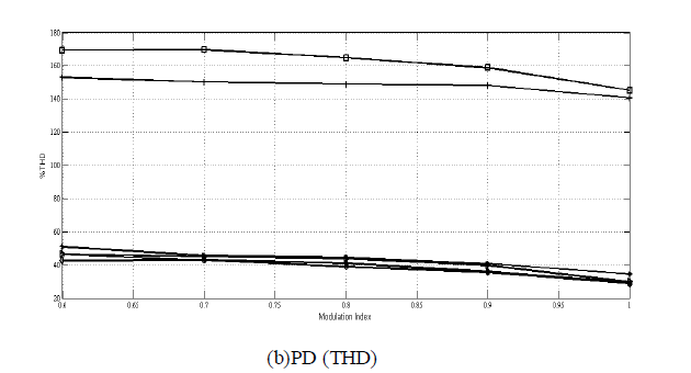 |
| The above results shows the percentage of THD of MMC verses different modulation index for different continuous and discontinues waveforms and Phase disposition carrier waveform, where all carriers are in phase. |
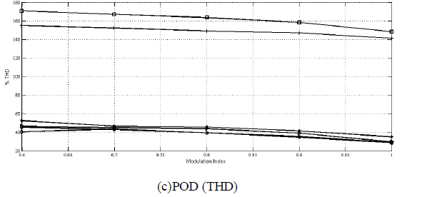 |
| The above results shows the percentage of THD of MMC verses different modulation index for different continuous and discontinues waveforms and Phase opposite disposition carrier waveform, where all carriers above the zero value reference are in phase among them but in opposition with those below. |
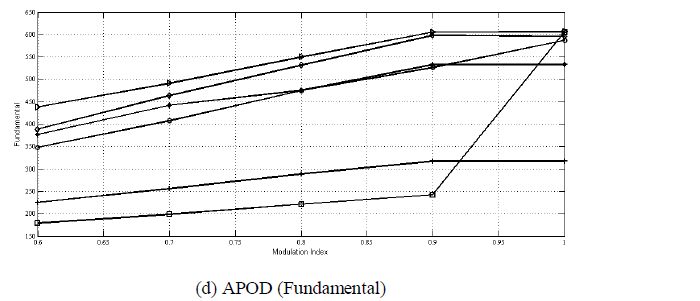 |
| The above results shows the fundamental value reference wave of MMC verses different modulation index for different continuous and discontinues waveforms and Alternate Phase opposite disposition carrier waveform |
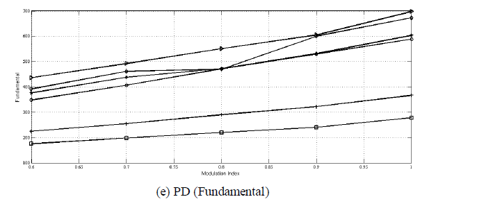 |
| The above results shows the fundamental value reference wave of MMC verses different modulation index for different continuous and discontinues waveforms and Phase disposition carrier waveform. |
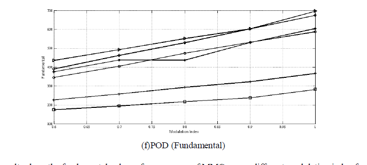 |
| The above results show the fundamental value reference wave of MMC verses different modulation index for different continuous and discontinues waveforms and Phase opposite disposition carrier waveform. |
| Different graph of THD verses Different Modulation index shown in figures. Fig 4(a) shows the characteristics of APOD in terms of THD verses Modulation index. . Fig 4(b) shows the characteristics of PD in terms of THD verses Modulation index. . Fig 4(c) shows the characteristics of POD in terms of THD verses Modulation index. . Fig 4(d) shows the characteristics of APOD in terms of Fundamental verses Modulation index. . Fig 4(e) shows the characteristics of PD in terms of Fundamental verses Modulation index. . Fig 4(f) shows the characteristics of POD in terms of Fundamental verses Modulation index. Where CMF is represented by ‘ ’, HMF is represented by ‘ ’, Where TMF is represented by Where NLMF-1, NLMF-2, NLMF-3, is represented by ‘ ’ ‘+’, ‘*’. |
 |
CONCLUSION
|
| The modular multilevel converter and different multi-carrier continuous and discontinuous PWM techniques.Have been discussed in this paper. THD and harmonic spectrum, from simulations with the MATLAB software have been reported. Comparison of the typical multicarrier continuous and discontinuous PWM techniques. the simulation results which are shown in fig IV(a) to IV(d) and Table II shows that multi-carrier discontinuous PWM methods gives more harmonics distortion in the output voltage because it does not cut often to carrier signal, while continuous modulation methods gives less distortion in the output voltage because the reference waveform is continuous and cuts to more points in the carrier waveform. The distortion in the output voltage is given without filter. Discontinuous modulation though gives high distortion, it gives low switching losses. Simulation results acknowledge the above opinions. |
References
|
- J. Rodriguez, J.S. Lai, F.Z. Peng, “Multilevel inverters: A survey oftopologies, controls, and applications,” IEEE Trans. Ind. Electron.,Vol. 49,pp.724-738, August 2002.
- N. Flourentzou, V.G. Agelidis, G.D. Demetriades, “VSC-based HVDC power transmission systems: an overview,” IEEE Trans. PowerElectr.,Vol.24, No.2, pp. 1-11, 2009.
- E. Acha, V.G. Agelidis, O. Anaya-Lara, T.J.E. Miller, “Power Electronic control in electric systems”, Butterworth-Heinemann, ISBN0750651261, January 2002.
- Nabae, I. Takahashi, and H. Akagi, “A neutral-point-clamped PWM inverter,” IEEE Trans. Ind. Appl., Vol. IA-17, pp. 518-523, 1981.
- Y. Cheng et al., “A comparison of diode-clamped and cascaded multilevel converters for STATCOM with energy storage,” IEEE Trans., onIndustrial Electronics, Vol. 53, no. 5, Oct 2006, pp. 1512-1521.
- T.A. Maynard and H. Foch, “Multilevel conversion: high voltage choppers and voltage source inverters,” in Proc. of IEEE Power Electron.Spec. Conf., 1992, Vol. 1, pp. 397-403.
- G. Carrara et al., “A new multilevel PWM method: A theoreticalAnalysis,” IEEE Trans Power Electronics, Vol. 7, No. 3, July 1992, pp. 497-505.
- Shoji Fukuda and Kunio Suzuki, “harmonic evaluations of carrier basedpwm methods using harmonics distortion determining factor”, IEEETrans. Power Electr., Vol. 24, No.2, pp. 1-11, 2009.
- GeorgiosS.Konstantinou, VassiliosG.Agelidis, “Performance EvaluationOf Half-Bridge CascadedMultilevel Converters Operated withMulticarrier Sinusoidal PWM Techniques”2009 IEEE ICIEA conference-jully2009,pp-3399-3404
- M. Hagiwara and H. Akagi, "PWM Control and Experiment on Modular Multilevel Converters," IEE Power Electronic Specialist ConferenceRhodes, 15-19 June 2008, pp. 154-16.
- LiQiang, He Zhiyuan, Tang Guangfu, “Investigation of the HarmonicOptimizationApproaches in the New Modular MultileveConverters”IEEE transaction on industrial application 5, september/octomber-2010.vol.no-35,.
- Ke Li, and Chengyong Zhao, “ New Technologies of Modular MultilevelConverter for VSC-HVDC Application” IEEE 1st Power Electronic& Drive Systems & Technologies Conferenc- June 2010 pp.378-385.
- H. MohammadiPirouz, &M.TavakoliBina ,“New Transformer less STATCOM Topology for Compensating Unbalanced Medium-VoltageLoads” 1st Power Electronic &Drive Systems &Technologie Conference- Jan 2003, pp. 1307–1312.
- Grain. P. Adam, O. Anaya-Lara, G. Burt, J. McDonald,“Transformer+less STATCOM based on a five-level modular multilevel converter”IEEE Trans. Industrial Electronics, Vol. 52, No. 1, February 2005, Pp.190- 196.
- AndrzejM.Trzynadiowski, “ An Overviews of Modern PWM Techniques for Three-Phase, voltage-controlled, voltage sourceInverters”inProc.of the IEEE International Symposium on Industrial Electronics,(ISIE)’96, 17-20 June 1996 pp.25-31
- G. P. adam, o. Anaya_Lara, G.M. Burt, D. Telford, B.W. Williams and J. R. McDonald, “modular multilevel inverter; pulse width modulationand capacitor balancing technique,” IET Power Electronics,2010,vol.3Issue 5, pp. 702-715.
|