Keywords
|
| hybrid fault current limiter, solid-state fault current limiters, superconducting fault current limiters radial power distribution system. |
I. INTRODUCTION
|
| Over the past decades, superconducting technology have been grown in various area. Especially superconducting fault current limiters have been developed. SFCL decreases the fault current and reduces the adverse effect on the power system ultimately this can make the capacity of the circuit breakers small. Moreover, SFCL can provide additional advantage as the improvement of voltage sag [1].Reference [1] presents the assessment method of voltage sag using the Information of Technology Industry Council (ITIC) curve when SFCL is applied to radial power distribution system. Reference [3] and [4] presents the improvement of voltage sag by installing the various fault current limiters. Reference [13] presents the IGCT based solid-state fault current limiters. Reference [14] presents the hybrid fault current limiter based on resonant LC circuit. Voltage sag is evaluated by magnitude and duration. In general the series connected impedance such as SFCL improves the magnitude of sag where as it may worsen the duration of sag because of the delayed trip time of the protective device by the decreased faults current. These effects of various FCL on voltage distortion should be evaluated. In this paper we assess the impact of various types of FCL on voltage distortion and fault current in radial power distribution system. In section II we model various types of FCL. In section III the voltage distortion occurred by faulty current is explained and fault current magnitude is also analyzed. In section IV we evaluate the voltage distortion magnitude using various FCL even we evaluate the fault current magnitude using various fault current limiters. |
II. LITERATURE REVIEW
|
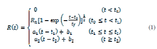
| In this paper we design the resistive type superconducting fault current limiter based on [1], [5]-[10]. The impedance of SFCL according to time (t) is given in (1). Where Rn and tf represents the impedance being saturated at normal temperature and time constant respectively. In addition to t1 , t2 represent quench start time, the first recovery time and second recovery time |
 |
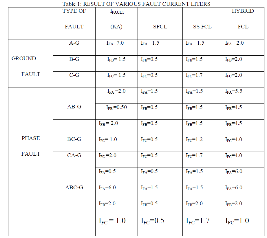
| The solid state fault current limiters developed by wanmin [13] consist of diodes, reactor and self turned- off igct switches by optimizing the size of the inductor and with the introduction of switches that can handle high power, this type of FCL can be made relatively compact in size. the author in [13] provides a good overview of the technical detail involved in the model. the hybrid fault current limiter developed by h.arai [14] is based on the resonance characteristics exhibited when an inductor and capacitor are in series with each other. the performance of various types of fault current limiters are being analyzed on the basis of fault current limitation as well as limitation in the voltage distortion during the occurrence of fault. the result of superconducting fault current limiter is being analyzed with solid state as well as hybrid fault current limiters |
III. VOLTAGE DISTORTION AND FAULT CURRENT MAGNITUDE
|
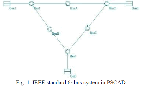
| When fault occurs in a power distribution system the automatic reclosure or circuit breaker with over current relay (OCR) and reclosing relay will open to clear the fault and automatically reclose after a time delay. This reclosure behavior can take place several times in an effort to establish a continuous service when a temporary fault occurs [11].Fig. 1 depicts the IEEE standard 6- bus system in PSCAD |
 |
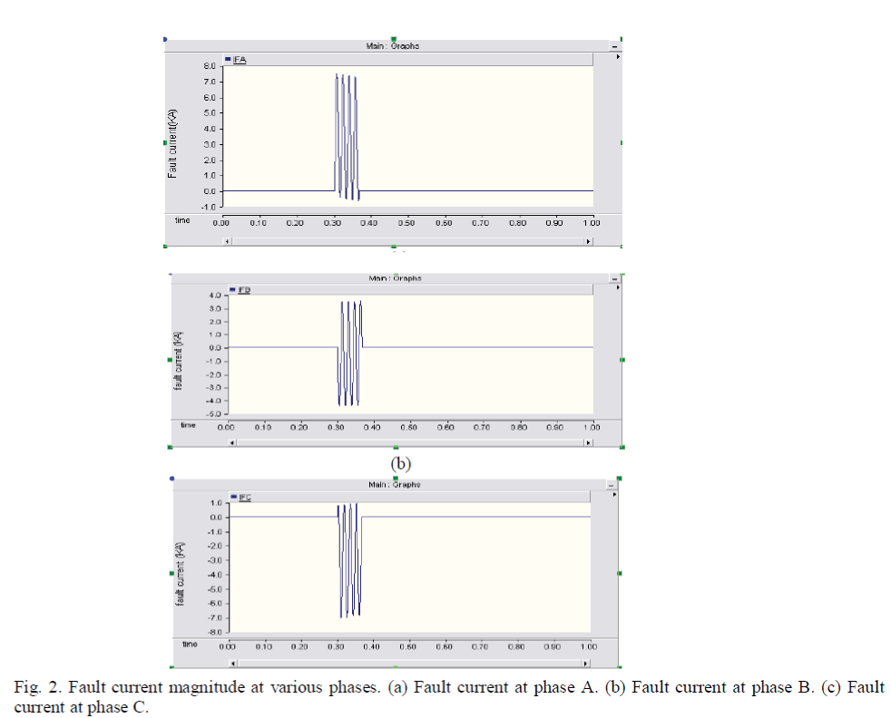
| This IEEE model is stimulated in the PSCAD with the above mentioned specification as prescribed in the table and various results are being analyzed Fig. 2 depicts the various fault current at various phases during the occurrence of fault. Fig. 2 (a) depicts fault current in phase A, likewise Fig. 2 (b) depicts fault current in phases B and Fig. 2 (c) depicts fault current in phase C |
 |
| When a fault occurs, the customer at each feeder experiences different magnitude of voltage according to various factors such as line impedance, fault location and so on. Generally, a voltage magnitude at the bus near to the secondary side of the main transformer during fault can be represented by the equation (2), ignoring the fault impedance and a three phase fault is applied. The source voltage is at 1.0 p.u. |
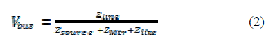 |
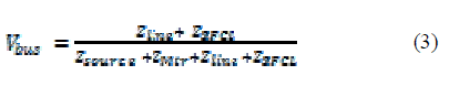
| Where Zsource , ZMtr and Zline are the source, line, transformer impedance from source to fault location respectively. Equation (2) can also approximately represent the voltage magnitude at the customer on all the neighboring bus. In this paper voltage magnitude is focused than duration. |
IV. ASSESSMENT OF IMPACT OF VARIOUS FCL
|
| A. Superconducting Fault Current Limiters |
| If SFCL is installed to the power distribution system, the equation (2) is changed to equation (3) during fault. The voltage distortion is reduced than in the case without SFCL. |
 |
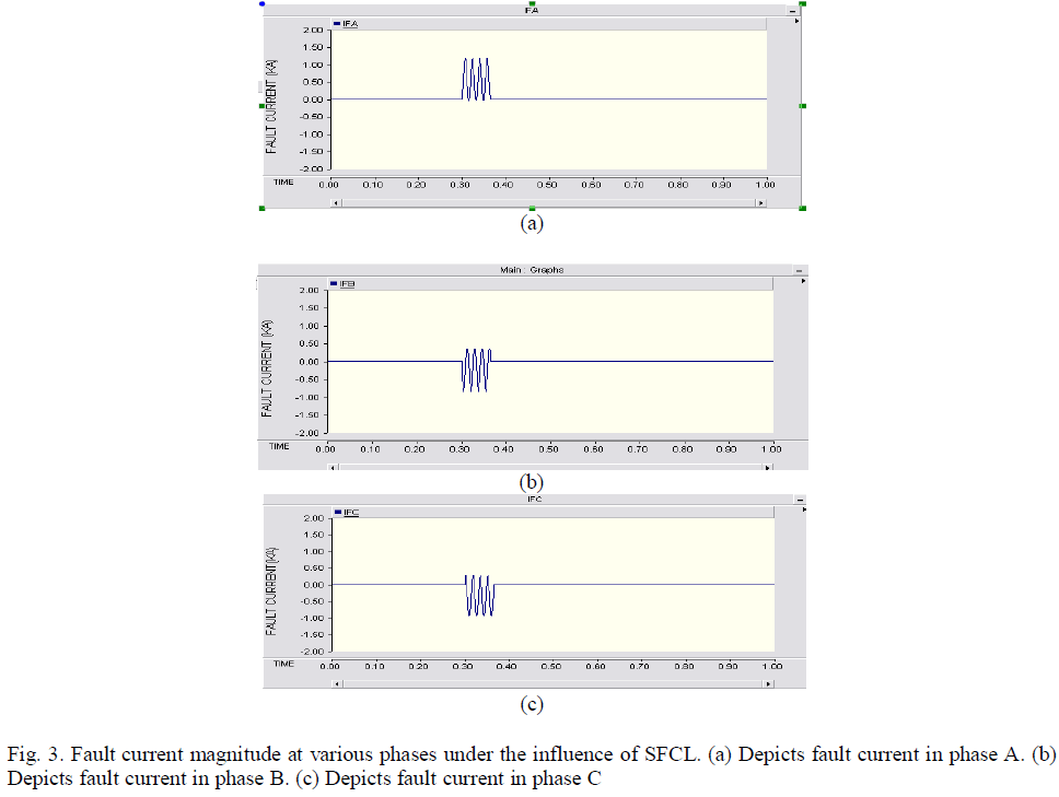
| The following segment explains the output waveforms obtained by the placement of various fault current limiters at the optimal location in order to reduce the fault current as well as reduction in the voltage distortion that is caused during the occurrence of fault. The current section discuss the performance of superconducting fault current limiter followed by the performance analysis of other two types of fault current limiter i.e. Solid State fault current limiter and Hybrid fault current limiter. The Fig. 4 and Fig. 5 depict the result obtained using superconducting fault current limiter. Fig. 4 depicts the reduction in fault current in each phase under the influence of SFCL. Fig. 3 (a) depicts fault current in phase A, likewise Fig.3 (b) depicts fault current in phases B and Fig. 3 (c) depicts fault current in phase |
 |
| B. Solid-State Fault Current limitersq |
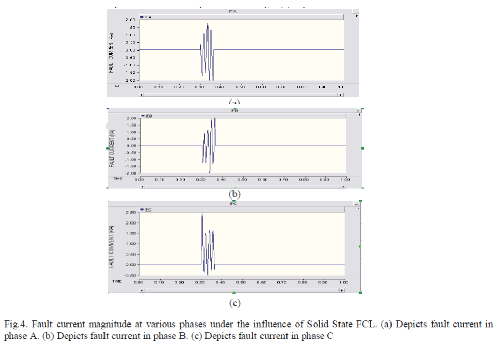
| The Fig 4 depict the impact of solid state fault current limiter on the fault current and the voltage distortion. Fig. 6 depicts the fault current in each phase under the influence of solid state FCL. Fig. 4 (a) depicts fault current in phase A, likewise Fig. 4 (b) depicts fault current in phases B and Fig.4 (c) depicts fault current in phase C. |
 |
| C. Hybrid Fault current limiter |
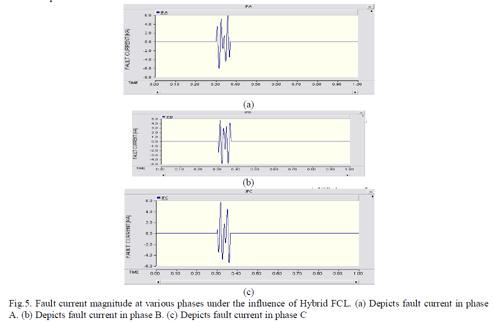
| The Fig.5 and depicts the impact of hybrid fault current limiter on the fault current and the voltage distortion. FCL. Fig. 5 (a) depicts fault current in phase A, likewise Fig.5 (b) depicts fault current in phases B and Fig. 5 (c) depicts fault current in phase C |
 |
V. CONCLUSION
|
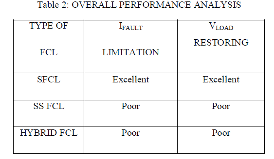
| In this paper, a comprehensive up-to- date review of various types of fault current limiters are analyzed and the behavior of each fault current limiters on the voltage distortion and the fault current limiting are also analyzed. From the above discussion we conclude that SFCL is more efficient on the basis of both fault current limitation as well as reducing the distortion in the voltage profile when comparing its performance with other two fault current limiters. |
 |
 |
References
|
- J.-F. Moon, S.-H. Lim, J,-C. Kim and S.-Y. Yun, “Assessment of the impact of SFCL on the voltage sag in power distribution.”IEEETrans. Appl. Supercond., vol. 21, no. 3, pp. 2161-2164, Jun.2011.
- L. Ye, L. Z. Lin, and K.-P.Juengsi, “Application studies of superconducting fault current limiter in electrical power system.” IEEE Trans.Appl. Supercond.,vol. 12, no.1, pp.900-903, Mar 2002.
- J.C. Das, “Limitations of fault current limiters for the expansion of electrical distribution system.” IEEE Trans. Ind Appl., vol. 33, no. 4,pp.1073-1082, Jul/Aug.1997
- F. Tosato and S. Quaia, “Reducing voltage sags through fault current limitation.” IEEE Trans Power Del., vol.16, no. 1, pp. 12-17,Jan.2001
- H. –R. Kim, H.-S. Choi, H.-R. Lim, I.-S. Kim and O.-B. Hyun, “Resistance of superconducting fault current limiters based onYBa2Cu3O7 thin film after quench completion.” Phys.C, Supercond., vol. 372-376, pp. 1606-1609, Aug. 2002.
- S. H. Lim, S.R. Lee, H.S. Choi and B.S. Han, “Analysis of operational characteristics of flux lock loop type SFCL combined with powercompensator.” IEEE Trans. Appl. Supercond., vol. 15, no. 2, pp. 131-134, Jun.2005.
- H. –R. Kim, S.-W. Yim, S.-Y. Oh and O.-B. Hyun “Recovery in superconducting fault current limiters at low applied voltage.” IEEETrans. Appl. Supercond., vol.18, no. 2, pp. 656-659, Jun.2008.
- H. –R. Kim, S.-W. Yim, S.-Y. Oh and O.-B. Hyun “Analysis on recovery in Au/YBCO thin film meander line,” Progr. Supercond.,vol.9,no. 1, pp. 119-125, 2007.
- J.-F. Moon, S.-H. Lim, J.-S. Kim et al., “Analysis on the protection coordination on neutral line of main transformer in power distributionsubstation with superconducting fault current limiter.” Trans Korean Inst. Elect. Eng., vol.58, no. 11, pp. 2089-2094, Nov 2009.
- H.R. Kim, S.-W. Yim, S.-Y. Oh and O.-B. Hyun “Analysis on recovery characteristics of superconducting fault current.” In Proc. MT-20Conf. Magn. Technol., Philadelphia, PA, Aug. 27-31, 2007.
- J. Arrillaga, N.R. Watson and S. Chen, power system quality assessment. Chichester, U.K.: Wiley, 2000.
- J.-F. Moon, J.-S. Kim “Voltage sag analysis in loop power distribution system with SFCL” IEEE Trans. Appl. Supercond., vol. 23, no. 3,Jun.2013.
- F. Wanmin, Z.Yanli “A Novel IGCT based half controlled type fault current limiters in power electronics and motion control conference2006” IPEMC’ 06 CES/IEEE 5th international, 2006, pp 1-5
- H.Arai, M.Inba, T.Ishigohka, H. Tanaka, K.Arai, M. Furse “Fundamental characteristics of superconducting fault current limiters usingLC resonant circuit.” IEEE Trans. Appl. Supercond., vol. 16, pp. 642-645,2006
|