Keywords
|
| Multilevel Inverter (MLI), Asymmetrical Cascaded H-Bridge Multilevel Inverter(ACMLI), Level Shifted Carrier Based Sinusoidal Pulse Width Modulation (LSCPWM) Technique. |
INTRODUCTION
|
| Multilevel power conversion technology is a very rapidly growing area of power electronics with a good potential for further development [1]-[7]. The most attractive applications of this technology are in the medium voltage (2.3-13.8 KV)and high power range (0.2-40 MW), and include motor drives, power distribution, power quality and power conditioning applications [2]-[5]. Ordinary two level inverters cannot be used for high power and high voltage applications because of limitation in power handling capability and rating of the semiconductor devices [6]-[8]. To overcome the limited semiconductor voltage and current ratings, some kind of series and/or parallel connection will be necessary thereby allowing greater working voltages to be reached, which in turn increases the power they are able to handle [9]. Due to their ability to synthesize waveforms with a better harmonic spectrum and attain higher voltages, multi-level inverters are receiving increasing attention in the past few decades. The three most important topologies have been proposed for multilevel inverters [5]-[11]: diode-clamped (neutral-clamped); capacitor-clamped (flying capacitors) and cascaded H-Bridge Multilevel inverter with separate dc sources.Diode clamped requires more no of diodes and flying capacitor has capacitor balancing problem. In addition, several other topologies have been proposed in the literature [5], [7]. The cascaded H-bridge multilevel inverters having more no of advantages such as modular structure and less no of components required compare to other topologies. It is one of the topologies proposed for drive applications which meet the requirements such as high power rating with reduced THD and switching losses. |
| For higher-level operation, cascaded H-Bridge multilevel inverter are preferred but major disadvantage is requirement of multiple dc-sources, which is not feasible in many applications.With an aim to reduce the number of dc sources required for the cascaded H-Bridge multilevel inverter, a focuses on asymmetrical cascaded H-Bridge multilevel inverter that uses unequal dc sources in each phase to generate a three- phase equal step multilevel output [15]. There are many modulation techniques are discussed in the literature to control the multilevel inverter such as selective harmonic elimination [5], space vector modulation [7], carrier-based sinusoidal pulse width modulation [9], etc. In this paper, level shifted carrier-based SPWM technique is used for ACMLI because of its advantages of simple logic and easy implementation. |
SYMMETRICAL & ASYMMETRICAL CASCADED H-BRIDGE MULTILEVEL INVERTER
|
| A relatively new power converter structure, cascaded H-Bridge multilevel inverters with separate DC sources is introduced here. This new converter can avoid extra clamping diodes or voltage balancing capacitors. Fig. 1 shows the basic structure of the cascaded H-Bridge multilevel inverter with separate DC sources for three phase configuration. The AC terminal voltages of different level inverters are connected in series. The phase output voltage is synthesized by the sum of inverter outputs. Each single-phase full bridge inverter can generate three level outputs, +Vdc, 0, and - Vdc. This is made possible by connecting the DC sources sequentially to the AC side via the four semiconductor power devices. Fig. 2 illustrates the voltage polarities (positive, zero and negative polarities) for the first H-bridge cell according to the switching states. |
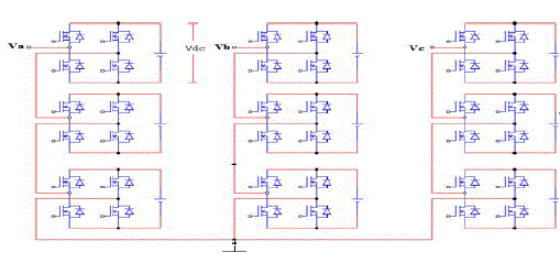
Fig.1 Three phase Y-configured ACMLI |
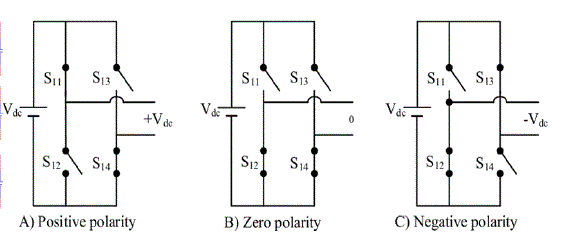
Fig. 2 Output voltage polarities for the first H-bridge cell |
| This method introduces the idea of using separate DC sources to produce an AC voltage waveform which is nearly sinusoidal. Each H-bridge inverter is connected to its own DC source. By cascading the output voltage of each Hbridge inverter, a stepped voltage waveform is produced. For many applications it is difficult to use separate dc sources and too many dc sources will require many long cables and could lead to voltage imbalance among the dc sources. To reduce the number of dc sources required for the cascaded H-bridge multilevel inverter, an asymmetrical topology is proposed which uses lesser number of bridges and dc sources. This scheme therefore provides the capability to produce higher voltages at higher speeds with low switching frequency which has inherent low switching losses and high converter efficiency. |
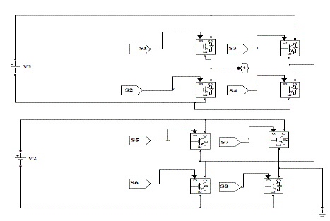
Fig. 3 One phase leg of an ACMLI for 7 and 9-level |
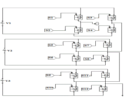
Fig.4 One phase leg of an ACMLI for 15 and 27-level |
| In ACMLI, DC voltage with ratio binary and ternary are the most popular. In binary progression within H-Bridge inverters, the DC voltages having ratio 1:2:4:8….:2N-1 and the maximum voltage output would be (2N-1) Vdc and the voltage levels will be (2N+1-1). While in the ternary progression the amplitude of DC voltages having ratio 1:3:9….:3 N-1 and the maximum output voltage reach to ((3N-1)/2) Vdc and the voltage levels will be 3N, where N is the no. of H-Bridges. Fig.3 and Fig. 4 shows the power circuit of an asymmetrical cascaded H-Bridge multilevel inverter. For clarity of the figure, only one phase leg is shown in the figure. For 7 and 9-level ACMLI only two H-Bridges are needed with binary and ternary ratio respectively as shown in Fig. 3 and for 15 and 27-level ACMLI three H-Bridges are needed with binary and ternary ratio respectively as shown in Fig. 4. In this topology, each cell has separate dc link voltages which are in different ratios for obtaining different levels. Each H-Bridge cell may have positive, negative or zero voltage. Final output voltage is the sum of all H-bridge cell voltages and is symmetric with respect to neutral point, so the number of voltage levels is odd. The output voltage of each H-Bridge cell for both binary and ternary ratio are given in Table. 1 and Table. 2 respectively. |

Table. 1 Output voltage of each H-Bridge cell for 7 and 15-level |
Table. 2 Output voltage of each H-Bridge cell for 9 and 27-level
 |
| Seven level asymmetrical cascaded H-Bridge multilevel inverter consists of two H-bridges. The dc voltage having ratio 1:2 Vdc and the maximum output voltage is 3Vdc. The switching states of 7-level output voltage is shown in Table. 3. |

Table. 3 Switching states of 7-level output voltage |
| Nine level asymmetrical cascaded H-Bridge multilevel inverter also consists of two H-bridges. But the dc voltage having ratio 1:3 Vdc and the maximum output voltage is 4Vdc. The switching states of 9-level output voltage is shown in Table. 4. |
Table. 4 Switching states of 9-level output voltage
 |
| Fifteen level asymmetrical cascaded H-Bridge multilevel inverter consists of three H-bridges. The dc voltage having ratio 1:2 Vdc and the maximum output voltage is 7Vdc. The switching states of 15-level output voltage is shown in Table. 5. |

Table. 5 Switching states of 15-level output voltage |
| Twenty-seven level asymmetrical cascaded H-Bridge multilevel inverter also consists of three H-bridges. But the dc voltage having ratio 1:3 Vdc and the maximum output voltage is 13Vdc. The switching states of 27-level output voltage is shown in Table. 6. |
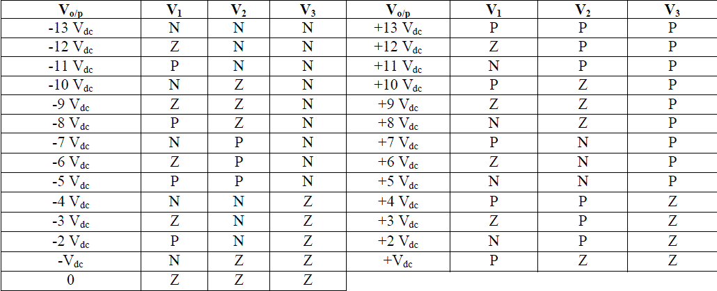
Table. 6 Switching states of 27-level output voltage |
CARRIER BASED SINUSOIDAL PWM TECHNIQUE
|
| This highly conventional technique is based on the comparison of a sinusoidal reference with carrier signals which are usually selected triangular and modified in phase or vertical positions to reduce the output voltage harmonic content. Due to simplicity and popularity of this technique, it will be analysed in this thesis in details and will be used as the modulator of the multilevel topologies. |
| The carrier-based modulation schemes for multilevel inverters can be generally classified into two categories: phaseshifted and level-shifted modulations. Both modulation schemes can be applied to the asymmetrical cascaded H-bridge multilevel inverters. Total harmonics distortion of phase-shifted modulation is higher than the level-shifted modulation. Therefore we have considered level-shifted modulation. An m-level proposed multilevel inverter using level shifted multicarrier modulation schemes requires (m-1) triangular carriers, all having the same frequency fc and amplitude Ac. The (m-1) triangular carriers are vertically disposed such that the bands they occupy are adjacent to each other. The reference waveform has amplitude of Am and frequency of fmand it is placed in the middle of the carriers. The reference wave is continuously compared with each of the carrier signals. There are three types of level shifted carrier-based PWM techniques as follows: |
A. Phase Disposition Technique (PD)
|
| The vertical offset of carriers for 7-level of ACMLI with PD technique is illustrated in Fig. 5. It can be seen that all carriers are adjacent to each other with same phase and the reference sine wave is placed in the middle of the carriers. Here, one sinusoidal wave is compared with six triangular signals. Similarly, for other levels one sinusoidal wave is compared with (m-1) triangular signals where m is the no. of levels. |
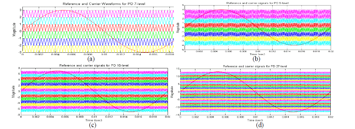
Fig. 5 Reference and carrier signals for PD technique: (a) 7-level (b) 9-level (c) 15-level (d) 27-level |
B. Phase Opposition Disposition Technique (POD)
|
| The vertical offset of carriers for all levels of ACMLI with POD technique is illustrated in Fig. 6. It can be seen that they are divided equally into two groups according to the positive/negative average levels. In this type the two groups are opposite in phase with each other while keeping in phase within the group. The reference wave is placed in the middle of the carriers.Here, one sinusoidal wave is compared with six triangular signals. Similarly, for other levels one sinusoidal wave is compared with (m-1) triangular signals where m is the no. of levels. |
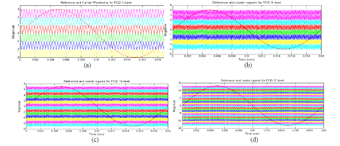
Fig. 6 Reference and carrier signals for POD technique: (a) 7-level (b) 9-level (c) 15-level (d) 27-level |
C. Alternative Phase Opposition Disposition Technique (APOD)
|
| The vertical offset of carriers for all levels of ACMLI with APOD technique is illustrated in Fig. 7. In this technique, all carriers are opposite in phase with each other and the reference wave is placed in the middle of the carriers. Here, one sinusoidal wave is compared with six triangular signals. Similarly, for other levels one sinusoidal wave is compared with (m-1) triangular signals where m is the no. of levels. |
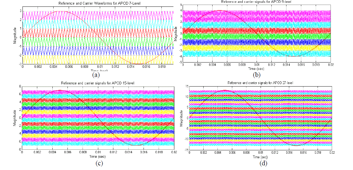
Fig. 7 Reference and carrier signals for APOD technique: (a) 7-level (b) 9-level (c) 15-level (d) 27-level |
STUDY CASE IMPLEMENTED IN MATLAB
|
| The simulation of three phase 7, 9, 15 and 27-level asymmetrical cascaded H-Bridge multilevel inverter is carried out using MATLAB/SIMULINK as shown in Fig 8. Here the subsystem for pulse generator is modeled where one reference wave (sine wave) and (m-1) carrier signals (triangular wave) are taken. First ((m-1)/2) triangular wave is applied across the positive half cycle of the sine wave and the second ((m-1)/2) triangular wave is applied across the negative half cycle of the sine wave. |
| Based on the concepts explained in modulation techniques, eight pulses are generated for 7 & 9-level and twelve pulses are generated for 15 & 27-level. These pulses are given to the switches in one phase leg of an ACMLI. Similarly the pulses are generated for remaining two phases, just by changing phase shifting angle of modulating signal by 120 degrees. Fig 9: represents the logic circuit of a 7-level. Based on this concept other levels of logic circuit are also designed. |
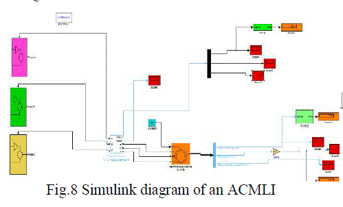 |
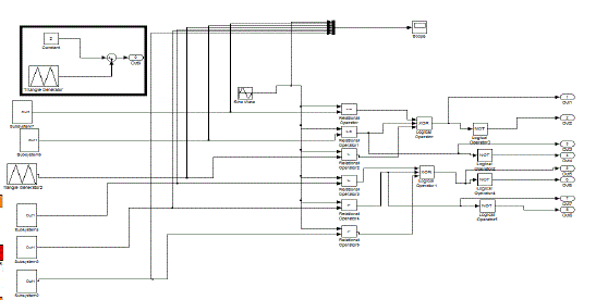
Fig. 9 Logic circuit |
RESULTS AND DISCUSSION
|
| The performance is analyzed for all levels of ACMLI with different level shifted SPWM technique feeding a three phase squirrel cage induction motor. Also the harmonic analysis is being carried out for all levels of ACMLI with different SPWM technique i.e., PD, POD, APOD.All the resulting waveforms are discussed here in detail and it is clear that the THD is reduced by increasing the levels of ACMLI. So it can be concluded that the higher level of ACMLI gives low THD. For comparison of all levels of ACMLI fed induction motor drive, it is important to examine few parameters of the system. The parameters & ratings of a three phase squirrel cage induction motor and the system are specified in Table. 7. |

Table. 7 Parameters & ratings of a three phase induction motor and the system |
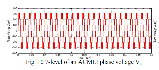
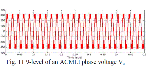
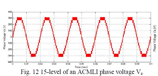
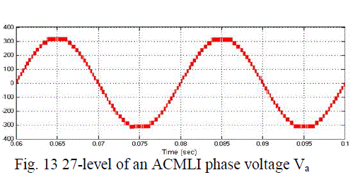
| The output voltage waveform for phase A of 7, 9, 15 and 27-level ACMLI with three phase squirrel cage induction motor as a load using LSCPWM technique is shown in Fig. 10-13. It can be observed that there are few notches in the voltage waveform and 27-level voltage waveform is closed to sinusoidal waveform as shown in Fig. 13. |
  |
  |
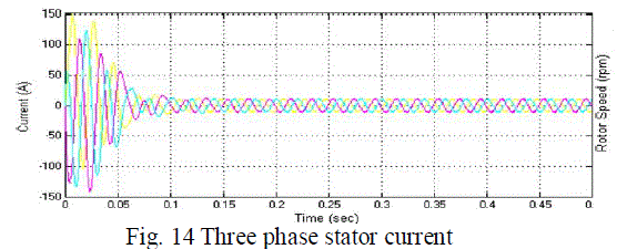
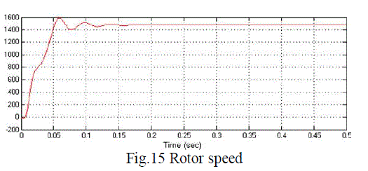
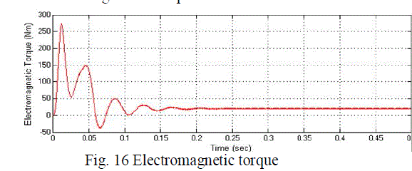
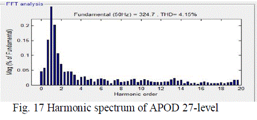
| The three phase stator current are much closer to sinusoidal as shown in Fig. 14. The speed response of the three phase squirrel cage induction motor driven by the proposed converter has been shown in Fig.15. The peak overshoot is 1600 rpm and starts to settle down after peak value. At time 0.15 sec it completely settled down to rated speed 1440 rpm. In steady state, a small speed ripple is introduced due to harmonics of the output voltage, specifically the fifth and seventh harmonics. Similarly the torque shown in Fig. 16 contains some ripples because of harmonics. From Fig.17 which represents the harmonic spectrum, it can be observed that the total harmonic distortion (THD) of the 27-level ACMLI using APOD technique for phase voltage A is 4.15% at a modulation index of 1 and within limit prescribed by power quality standards |
  |
  |
| ACMLI |
| The comparison between all the levels of ACMLIis shown below in Table. 8.Performance indices like THD%, (indicating the amount of DC bus utilization), Crest Factor (CF) and Form Factor (FF) related to power quality issues have been evaluated, presented and analysed. The results of multilevel inverter systems are compared with different sinusoidal pulse width modulation techniques. It is observed that the total harmonic distortion produced by the 27- Level is 4.15%which is less than the other levels of ACMLI and it is also observed that by using APOD technique we get less THD by comparing other techniques. |

Table. 8 Performance comparison of all levels of ACMLI |
CONCLUSION
|
| The lower amount of disturbances is one of the more frequently mentioned advantages for multilevel inverters. It seems that the biggest reason for using multilevel inverters is to lower the THD so that less filters needs to be used. Compared to the NPCMLI and CCMLI, the CMLI requires fewer components, every voltage level requires the same amount of components. However, the numbers of sources are higher, for the phase-leg to be able to create a number of m voltage levels.To reduce the number of dc sources required for the cascaded H-bridge multilevel inverter, an asymmetrical topology is proposed which uses lesser number of bridges and dc sources. This scheme therefore provides the capability to produce higher voltages at higher speeds with low switching frequency which has inherent low switching losses and high converter efficiency.The THD of the Phase Voltage of all levels of ACMLI is studied under different level shifted carrier based sinusoidal pulse width modulation techniques such as PD, POD, and APOD and the less THD is observed for 27 level ACMLI and it also concluded that APOD is the best technique. |
References
|
- Calais M., Borle L. G. and Agelidis V. G., “Analysis of Multicarrier PWM Methods for a Single-Phase Five-Level Inverter,” IEEE PowerElectronics Specialists Conference, Vol. 3, pp. 1173-1178, 2001.
- Rodriguez, J., Lai, J. S. and Peng, F. Z., “Multilevel Inverter: ASurvey of Topologies, Controls and Applications,” IEEE Trans. on IndustrialElectronics, Vol. 49, No. 4 pp. 724-738, 2002.
- Mariethoz, S. and Rufer, A. C., “Design and control of asymmetrical multi-level inverters,” in Proc. IEEE 28th Annual Conference, IECON 02,Vol. 1, pp. 840-845, 2002.
- Feel-Soon Kang, Member, IEEE , Sung-Jun Park, Member, IEEE , Man Hyung Lee, Senior Member, IEEE , and Cheul-U Kim, Member, IEEE,“An efficient multilevel-synthesis approach and its application to a 27-Level inverter,” IEEE transactions on industrial electronics, vol. 52, no.6,December 2005.
- Azli, N.A. and Choong, Y.C. (2006), “Analysis on the performance of a Three- phase Cascaded H-Bridge Multilevel inverter,” in Proc. FirstInternational Conference on Power and Energy PECON, Putrajaya, Malaysia, pp. 405-410, 2006.
- Far, Z. D., Radan, A. and Far, M. D., “Introduction and Evaluation of novel multi-level carrier based PWM strategies using a generalizedalgorithm,” in Proc. European Conference on Power Electronics and Applications, EPE’07, pp. 1-10, 2007.
- RodrÃâñguez, J., Berne, S. T., Wu, B., Pontt, J. and Kouro, S., “Multilevel voltage-source-converter topologies for industrial medium voltagedrives,” IEEE Trans. Ind. Electron., Vol. 54, No. 6, pp. 2930-2945, 2007.
- Jeevananthan, S., Nandhakumar, R., and Dananjayan, P., “Inverted Sine Carrier for Fundamental Fortification in PWM Inverters and FPGABased Implementations,” Serbian Journal of Electrical Engineering, Vol. 4, No. 2, pp. 171-187, 2007.
- Aghdam, M. G. H., Fathi, S. H. and Gharehpetian, B., “Analysis of multicarrier PWM methods for asymmetric multilevel inverter,” in Proc.3rd IEEE Conference on Industrial Electronics and Applications, ICIEA’08, pp. 2057- 2062, 2008.
- Chaturvedi, P.K., Jain, S., Agrawal, P., Nema, R. K. and Sao, K. K., “Switching Losses and Harmonic Investigations in Multilevel Inverters,”IETE Journal of Research, Vol. 54, pp. 297-307, 2008.
- Zhong, D., Tolbert, L.M., Ozpineci, B. and Chiasson, J.N., “Fundamental Frequency Switching strategies of a Seven- Level Hybrid CascadedH-Bridge Multilevel Inverter”, IEEE Trans. on Power Electronics, Vol. 24, No. 1, pp. 25-33, 2009.
- Seyezhai, R. and Mathur, B. L., “Implementation and control of Variable Frequency ISPWM Method for an Asymmetric Multilevel Inverter”,European Journal of Scientific Research, Vol. 39, Issue 4, pp. 558-568, 2010.
- FaridKhoucha, SoumiaMounaLagoun, KhoudirMarouani, AbdelazizKheloui, and Mohamed El HachemiBenbouzid, Senior Member, IEEE,“Hybrid Cascaded H-Bridge Multilevel-Inverter Induction-Motor-Drive Direct Torque Control for Automotive Applications”, IEEEtransactions on industrial electronics, vol. 57, no. 3, march 2010.
- H. Abu-Rub, J. Holtz, J. Rodriguez and G. Baoming, "Medium-Voltage Multilevel Converters—State of the Art, Challenges, andRequirements in Industrial Applications", IEEE Transactions on Industrial Electronics, Vol. 57, No. 8, pp. 2581-2596, August 2010.
- Mrs. N. Booma, Assistant Professor, Dept. of Electrical and Electronics Engineering an Nagisetty Sridhar PG Student, Department of Electricaland Electronics Engineering, Jerusalem College of Engineering, Chennai, India. IEEE, “Nine level Cascaded H-bridge Multilevel DC-LinkInverter”, PROCEEDINGS OF ICETECT, 2011.
|