Keywords
|
| Photovoltaic (PV) system, solar water pump set, dc–dc Boost Converter, MPPT, Diode Clamped Inverter, SVPWM, FPGA, LC filter , PI Controller Three phase induction motor, |
I.INTRODUCTION
|
| The drinkable water is not available for millions of people in various countries due to the non availability of electrical supply in rural areas, where the supply of water is mainly from the rain or from rivers. In such places, the water management through photovoltaic (PV) system is the most efficient and promising way to solve this problem. Even though commercial converters like fuel cell (lead–acid. Lithium-ion batteries) and dc motors available to drive the water pump and giving higher efficiency due to the drawback of the batteries used for pumping system generally have low life span nearly two years which is too low when compared with PV module life of 20 years, requires frequent maintenance and replacement. Whereas PV energy source is cheaper and can reach the poor people need these systems. In this paper three phases IM is replaced by low voltage commercial DC motors due to higher maintenance cost, lower efficiency and also these low voltage DC motors are not frequently available in the market. Therefore this proposed work adopted the three phase induction motor which is available in local markets, and requires less maintenance cost than any other types of motors [14]-[15]. |
| The proposed PV module generates electrical energy directly from solar radiation. This model has to face the challenges like, it has to generate the maximum energy under variable restrictions and also maximize the amount of water pumped [1]. |
 |
| With these requirements a novel converter is modeled with high efficiency where the availability of energy is low, less cost to use where it is most needed, robustness therefore it needed less possible maintenance and finally has high life time usually 20 years. A new dc/dc boost converter and its control strategy suitable for PV water pumping are proposed [1]-[4] to fulfill the most of the aforementioned features. |
II. SOLAR CELL MODEL
|
| Photovoltaic cells are made with two semiconductor materials P-type and N-type. A PV cell is basically a light activated diode that generates a voltage when exposed to sun light. It also be known as a light-emitting diode. Basically PV system is a non-linear device due to its I-V characteristics and is usually described by its equivalent circuit shown in fig.2 and fig.3. The equivalent electrical model of a pv cell contains a current generator, a diode and two resistances. Shunt resistor indicates the leakage currents to the ground; the value of shunt resistor is about 1000 ohms. Series resistor indicates the internal resistance of leads connects to the solar cell and the value of series resistance is 0.001 ohms. |
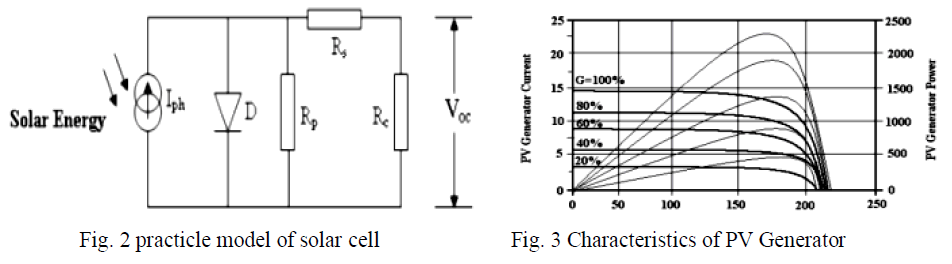 |
| Individual solar cells will offer low voltages (typically 0.5V-0.7V), therefore these cells are usually connected in series or in parallel according to our requirements. The PV array is nothing but the connection of number of solar PV modules. A single unit of PV module can satisfy the requirements of a household. Equations : |
 |
III. PROPOSED CONVERTER
|
| A single PV module is designed in this paper to ensure low cost and for our convenience. This proposed model can drive the motor in the range of 1/3 hp, it is enough to pump the water for single family. The simple operation of this proposed model is, the PV system generates the electrical energy which is in the form of dc output is in the range of 0.5v – 0.6v, thereby to improve the voltage level this low voltage is fed to the DC – DC Boost converter, the output of the boost converter is now fed to the three phase inverter to convert high level DC voltage into AC voltage. In this paper three level diode clamped inverter is presented [5] with the SVPWM controlling technique. By using SVPWM technique the output voltage enhanced when compared to SPWM technique and also it uses all the states in state vector model i.e. SPWM technique couldn’t use the states (000 and 111). Because of the two states, this proposed scheme is better than SPWM technique. As the operating characteristic of the PV panel is low, a dc-dc boost converter is needed to have a large voltage conversion ratio. MPPT technique of solar PV system is used to track the maximum amount of power even in cloudy condition. |
| Current fed converter is proposed due to the advantages over the voltage fed converter. Voltage fed converters has large input filter capacitor due to high input current ripple and also has large transformer turns ratio to boost the output voltage, therefore voltage-fed converters are not suitable for water pumping applications [19]. Current fed converters generally has an inductor at the input side, thereby having low input current ripple and eliminates the input capacitor. In general current fed converter is derived from the boost converter and having high step-up voltage conversion ratio, this eliminates the need of transformer turns ratio. In this paper, boost converter is proposed due to its small components size, more efficiency and simplicity. Besides, the input current is circulated through the boost inductor ripple free, this feature reduced the oscillations at the operation of PV module, thereby easier to achieve the MPPT. |
VI. MPPT CONTROL
|
| The operating point of the PV system is kept at the maximum power point by using MPPT technique. MPPT is one of the hill-climbing algorithms, which is most widely used in PV applications due to its fast dynamic response and simple implementation. Working of MPPT algorithm is mainly based on the nature of the power curve of the PV panel. This power curve can be separated into two sides; one is to the left and other is to the right side of the maximum power point. To get closer to the operating point first analyze the variation of power and voltage then figure out, correct operating region PV panel and adjust the reference voltage. PI controller is used to rise or to condense the motor speed based on this reference voltage. |
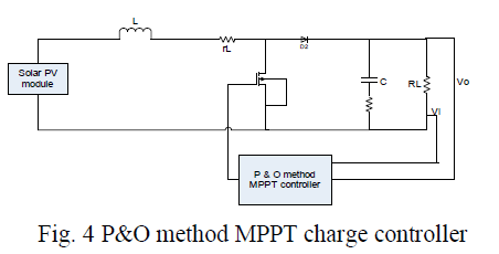 |
| The term fill factor (FF) is the combination of open circuit voltage and short circuit current of solar PV panel, the maximum power from the panel determined by fill factor and it can also be defined as the ratio of maximum power obtained from solar panel to the product of open circuit voltage and short circuit current. There are several types of MPPT algorithms namely perturb-and-observe (P&O), incremental conductance and constant voltage etc. The first two methods are often referred to as hill climbing methods, |
V. CLOSED LOOP DC-DC BOOST CONVERTER
|
| DC-DC Boost converter will step up the low level DC voltage magnitude (0.5v to 0.7v) into high level DC voltage magnitude. Generally Boost converter operates either in charging mode or in discharging mode, ON and OFF control of the suitable switch decides these modes of operation. Boost converter Circuit consists of an inductor at the source side, a diode and a high frequency switch as main elements in the circuit as shown below. |
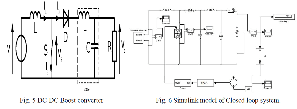 |
| The relationship between V0 and Vs is given as: |
 (3) (3) |
| Fig.6. Shows the Closed loop system of DC-DC boost converter, Output voltage is sensed and it is compared with a reference voltage. The error is processed by a FPGA controller; output of FPGA controller adjusts the pulse width to maintain the output voltage constant, input voltage and output voltage of closed loop system. The output voltage reduces and reaches the set value. |
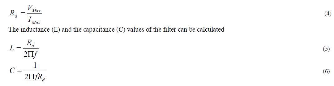
VI. LC- FILTER MODELING
|
| In this paper, LC-filter is modeled. It is a second order filter because it has to energy storage elements L and C. when compared to L-filter, it has better filtering ability. The configuration of LC filter is easy to design. The block diagram of an LC-filter is shown below |
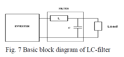 |
| The first step in filter designing is to find the best filter. Calculation of designed impedance is the second step. The final step is to equating the L and C values from the second step using. The impedance form can be calculated by using the below equation. |
 |
VII. MULTI LEVEL INVERTER
|
| Multilevel inverters are frequently used in Industries for high power applications in the range of MW level. Most of the industries having high power ac drive. These high power ac drives having a difficult when connected to the medium voltage power supplies. This problem has been conquering by multilevel inverters (MLI) with higher voltage levels [15]. Three diode clamped level inverter is proposed in this paper, for water pumping applications and the output of this inverter is fed to the induction motor which drives the water pump effectively [14]. MLI having clamping switches, capacitors, and voltage sources. High power can be handled when compared with conventional two level inverters. By using proper PWM scheme [5]-[8] to the proposed three level diode clamped inverter, harmonics are effectively reduced consequently improves efficiency [15]. The advantage of this three level inverter does not need supplementary coupling transformer exhibits high quality output waveform. |
| Various topologies have been used for multilevel inverters: (1) neutral-clamped (2) flying capacitors and (3) Cascaded multi cell with separate dc sources. The adopted control strategies for multilevel inverters are: (1) SPWM technique (2) selective harmonic elimination method, and (3) Space-vector modulation (SVM). In this paper SVPWM is proposed as a controlling technique. |
VIII. SPACE-VECTOR PULSE WIDTH MODULATION (SVPWM)
|
| The output voltage of inverter is increased by using SVWPM technique with PWM signals [5]. In -1980s only this technique was proposed. This technique is the most powerful PWM technique for three-phase inverters. In this paper the output of the inverter is controlled by SVPWM technique used to improve the performance of the pumping system and to minimize the general power losses. Several PWM schemes are implemented with the Microprocessor technology, which helps to reduce the switching losses, harmonics and for precise controlling of inverter output. By using SVPWM technique the output voltage enhanced when compared to SPWM technique and also it uses all the states in state vector model i.e. SPWM technique couldn’t use the states (000 and 111) [14]. Because of the two states, this proposed scheme is better than SPWM technique. |
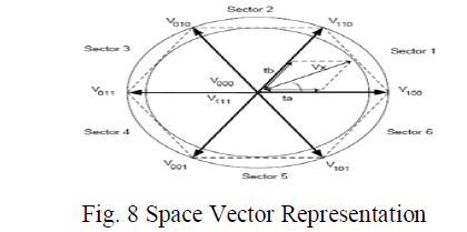
| The Voltage of DC bus can effectively utilize by SVPWM and generates less THD when compared with the SPWM. Maximum fundamental magnitude obtained by SVPWM controlled inverter is 90.6% and Maximum voltage is 15.5% [14]. Space Vector Representation is shown in fig.7 a reference line or vector is touching all the maximum points of vectors, there by a circle can be formed inside the state map. The region inside the state map and to the circle is called under modulation, the region outside the state model is known over modulation. These regions are depends on modulation index. |
 |
IX. FPGA BASED DESIGN
|
| Field Programmable Gate Array (FPGA) gives the easy way of implementing the PWM Generation for various Power electronic Applications. Generally FPGA has an interconnection between various logic gates. If any need arise after design on FPGA, it can be easily modified by changing the interconnection of logic blocks. This Reprogramming feature makes it suitable to design using FPGA [16]. Implementation using FPGA takes short time. Therefore this is the best way of implementing digital PWM Generators [8]. Implementation of FPGA-based digital controllers suitable for small designs hence less costly, hence in this thesis FPGA based PWM Generator technique is discussed.[5]-[8]. |
X. PWM CONTROL OF INVERTER
|
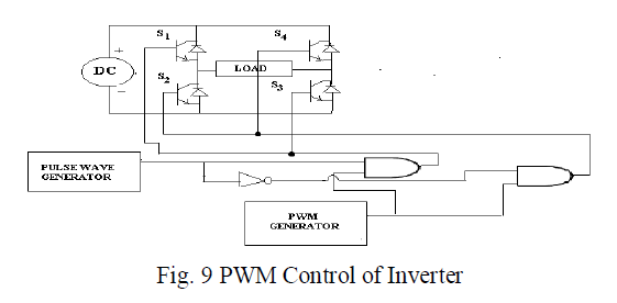
| The PWM control of a DC-AC converter is shown in Fig. 8. The PWM generator generates PWM control signal (VPWM), ANDED with rectangular pulse which is from pulse generator and is fed to switches S1 and S3 [5]-[8]. The inverted rectangular waveform is ANDED with PWM signal and is fed to switches S2 and S4. Thus input DC voltage is modulated into required AC voltage by providing proper turn ON and OFF time of power switches. |
| The power switches are generally of MOSFET or IGBT. These power switches make the inverter compatible in size. Inverter size is reduced by increasing the switching frequency of power switches. Therefore by proper selection of frequency of power switches by PWM Generator, we get optimized size of Inverter [5]. |
 |
XI. INDUCTION MOTOR
|
| One of the reasons for most widely using of Induction is due to its rugged construction, more reliability, cheap [14]- [15]. These IM motors require less maintenance because IM doesn’t have brushes and slip rings. In earlier days DC motors were used in most of the electrical drives due its variable speed characteristics. Now the power electronic technology makes the modern developments in speed controlling methods of the IM, led to their large scale use in almost all electrical drives. |
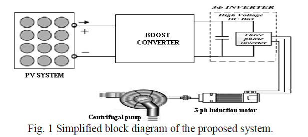
| Hence AC motors are tremendously chosen for fixed speed applications in industrial as well as in domestic applications where AC line power is available. Nearly 90% of motors are induction type motors in many applications viz. washers, air conditioners, industrial machinery, dryers, fans, vacuum cleaners, blowers, and other applications. In this paper this IM motor is used for water pumping system as shown in fig.1 |
 |
XII. RESULTS AND DISCUSSION
|
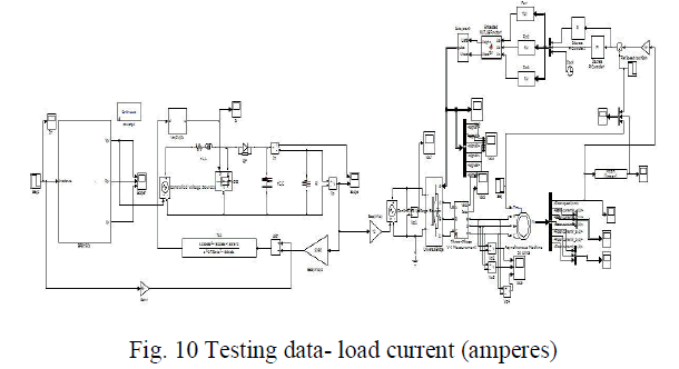
| Proposed system fed by Solar, is designed and simulated in MATLAB simulink environment, and the results are presented in this section. |
| Specifications of PV System: |
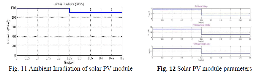
| Temperature variations range of PV System (T) = 298K |
| Irradiance (G) =1000W/m2-900W/m2. |
 |
| DC-DC Boost converter is designed for 24 to 48v with the following specifications. 24 to 60v, 50w Boost Converter Small Signal Transfer Function analysis: |
| From the specification of DC-DC boost converter, Plant Transfer function (Tp) is given by |
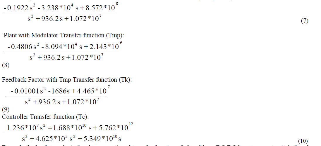 |
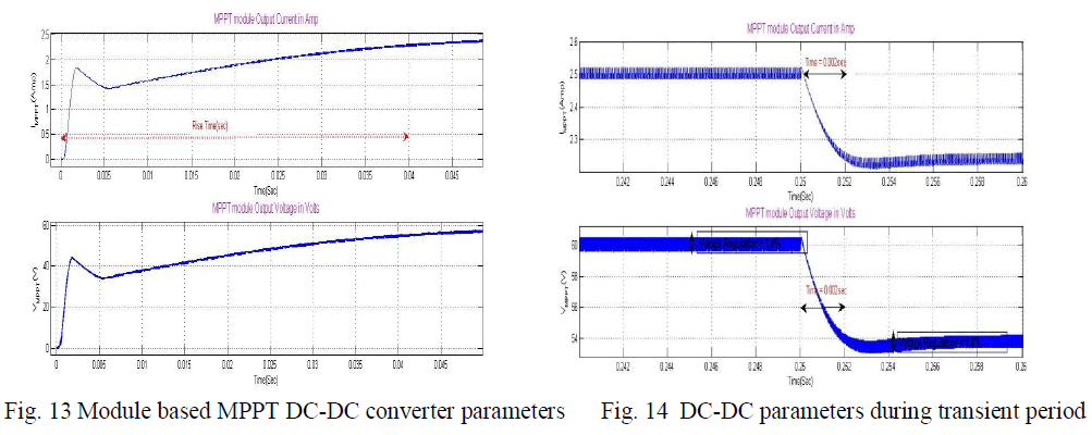
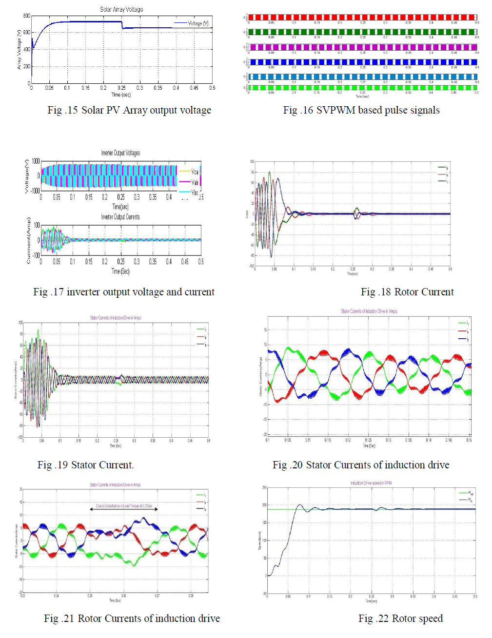
| From the bode plot analysis for above mentioned transfer function of closed loop DC-DC boost converter, it is found that that PM is 44.5o i.e., which meets required stability margin (30o-60o) of any practical converters. The output voltage and currents of MPPT based DC-Dc converter is fig.13. Additionally, transient parameters of DC-DC converter with MPPT algorithm is calculated with the help of MATLAB Simulink environment and presented in Fig.14. Fig. 15 represents the voltage of solar PV array which is formed by solar PV modules series connection. MPPT based boost converter series group fed to inverter which is operated in closed loop mode with V/F based SVPWM control algorithm and its waveforms are presented in Fig. 16 to Fig. 19. |
 |
 |
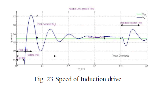 |
| Fig. 16 depicts that SVPWM based control signals which are controlling the inverter switches in closed loop mode to get required speed, and produce output parameters of inverter are presented in Fig. 17. In Fig. 18, actual speed of induction motor and reference speed is presented. Additionally, dynamic time domain parameters are calculated in MATLAB Simulink environment with sudden change in load at 0.25sec and presented in Fig. 19. |
XII. CONCLUSION
|
| Thus it allows each node with message to decide whether to copy the message to a path node by optimizing its transmission effort in order to provide a sufficient level of message delay. Using a channel selection scheme provides spectrum utilization while it minimizes the interference level to primary system. Using trustworthy algorithm, it improves the trustworthiness of the Spectrum sensing in CR-Networks. It enables network nodes to adaptively regulate their communication strategies according to dynamically changing network environment. |
References
|
- Hahn, “Technical maturity and reliability of photovoltaic pump systems,” in Proc. 13th Eur. Photovoltaic Solar Energy Conf., Nice, France,pp. 1783–1786.
- M. A. Vitorino and M. B. R. Correa, “High performance photovoltaic pumping system using induction motor,” in Proc. Brazilian PowerElectron. Conf., 2009, pp. 797–804.
- D. Tschanz, H. Lovatt, A. Vezzini, and V. Perrenoud, “A multi-functional converter for a reduced cost, solar powered, water pump,” in Proc.IEEE ISIE, 2010, pp. 568–572.
- M. A. Vitorino, M. B. R. Correa, C. B. Jacobina, and A. M. N. Lima, “An effective induction motor control for photovoltaic pumping,” IEEETrans. Ind. Electron., vol. 58, no. 4, pp. 1162–1170, Apr. 2011.
- S. R. Bowes and A. Midoun, “Suboptimal switching strategies for microprocessor controlled PWM inverter drives,” Proc. Inst. Elect. Eng.—Elect. Power Appl., vol. 132, no. 3, pp. 133–148, May 1985.
- M. Cacciato, A. Consoli, and V. Crisafulli, “A high voltage gain dc/dc converter for energy harvesting in single module photovoltaicapplications,” in Proc. IEEE ISIE, 2010, pp. 550–555.
- W. Li, L. Fan, Y. Zhao, X. He, D. Xu, and B. Wu, “High step-up and high efficiency fuel cell power generation system with active clampflybackforward converter,” IEEE Trans. Ind. Electron., vol. 59, no. 1, pp. 599– 610, Jan. 2012.
- P. M. Barbosa and I. Barbi, “A new current-fed, isolated PWM dc-dc converter,” IEEE Trans. Power Electron., vol. 11, no. 3, pp. 431–438,May 1996.
- B. Liu, C. Liang, and S. Duan, “Design considerations and topology selection for dc-module-based building integrated photovoltaic system,”in Proc. 3rd IEEE Conf. ICIEA, Jun. 3–5, 2008, pp. 1066–1070.
- D. Li, B. Liu, B. Yuan, X. Yang, J. Duan, and J. Zhai, “A high step-up current fed multi-resonant converter with output voltage doubler,
- R. Faranda and S. Leva, “Energy comparison of MPPT techniques for PV systems,” WSEAS Trans. Power Syst., vol. 3, no. 6, pp. 446–455,Jun. 2008
- M. Liserre, F. Blaabjerg, and S. Hansen, “Design and Control of an LCL-Filter-Based Three-Phase Active Rectifier,” IEEE Transactions onIndustry Applications, vol. 41, no. 5, pp. 1281– 1291, Sep. 2005.
- V. Blasko and V. Kaura, “A Novel Control to Actively Damp Resonance in Input LC Filter of a Three-Phase Voltage Source Converter,”IEEE Transactions on Industry Applications, vol. 33, no. 2, pp. 542–550, 1997.
- M. Rajendar Reddy, T. Brahmananda Reddy, 1. Amarnath and D. SubbaRayudu “Space Vector Based Novel and Simple Unified PulsewidthAlgorithm for Induction Motor Drives" IJIEC Volume 2, No.1, pp. 9- 32,2010.
- V. T. Somasekhar, B. Venugopal Reddy" A New Four-level Dual Inverter fed Open-end Winding Induction Motor Drive" IEEE PEDS20ll,PP.167-170 Singapore, 5 - 8 Dec-20ll.
- Koutroulis E., Dollas A. and Kazantzakis K., “High-frequency pulse width modulation implementation using FPGA and CPLD ICs”, Journalof Systems Architecture , Vol.52 (2006): pp. 332–344
- Rahim N.A. and Islam Z., “Field Programmable Gate Array-Based Pulse-Width Modulation for Single Phase Active Power Filter”; AmericanJournal of Applied Sciences, Vol.6 (2009): pp. 1742-1747
- Dancy A.P., Amirtharajah R. and Chandrakasan A.P., “High-Efficiency Multiple-Output DC–DC Conversion for Low-Voltage Systems”,IEEE Trans. on Very Large Scale Integration (VLSI) Systems, Vol. 8, No. 3, June 2000: pp.252-263
|