This paper describes that the measurement of different parameters at the poultry farm such as temperature, humidity, level of water and valve control. In this, automation will be done with help of above mentioned parameter. The hardware prototype also created by using MSP430 ultra low power microcontroller. Results have been defined in different views.
Keywords |
| MSP430, thermistor, humidity, level sensor, relay. |
INTRODUCTION |
| Instrumentation is a field in which the system or the device can respond with respect to environmental condition
change. Most of the industries familiar with sensors like temperature, humidity, pH, level, moisture, flow, leak detector etc.
Nowadays, with rapid development of poultry there is a large number of laying hens’ specialized culturist in rural areas.
Generally farmers don’t get appropriate funds and advanced tools for their farm. Especially they are lagging in the field of
automation and control the conditions of the farm. Hence it is severely affect the production of hens as well as eggs.
Therefore, enhancing the automation and special type of equipment in the small farms were necessary. |
| In this paper, initial idea has been described in terms of food feeding automation in time based manner and
monitoring the different parameters at egg incubation tray then automating the equipment by measuring them at the
particular band value. It also monitors the level of water in tank. Actually there is mechanical setup available for liquid
(water) flow for hens. Presently there are two types of incubation available namely artificial and natural. In natural method
there will be a hen for hatching process. The some pros are 1.No electricity 2. Hen does all the work 3. It will brood chicks
after they hatch. 4. High hatchability rate 5. Some breeds hatch better under hens (Nankin) than in incubators. 6. Good for
hatching small size of chicks per year. Even though it has some advantages there are some cons, 1.Hen sometimes breaks
eggs. 2. Will occasionally quit and get off nest.3. Hen sitting is 1 less not laying in the flock. 4. Can only sit on a small
size of eggs at a time. 5. Disease transmission from hen to chick. Hence in heavy industries they adopt incubators. It has
temperature range from 101 to 102 degree and relative humidity is about 50 to 60% and it consumes less electricity. |
 |
BASIC REQUIREMENTS AN EGG NEEDS TO HATCH |
| • Hatch Temperature 99 -102 Deg. F. |
| • Humidity 50%-65% RH |
| • Egg Turning at least 2x/day |
| • Air Flow air and gas exchange |
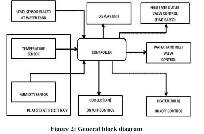
CREATION OF GENERALIZED BLOCK |
| Building the block diagram for an idea is necessary part in order to examine the overall operations of the defined
solutions. In this it describes temperature, level, humidity as an input and feed box valve control, water tank valve, cooler,
heater, and display unit as an output. The following figure 2 shows the block of the project. |
 |
PROPOSAL OF THE PAPER |
| Currently in poultry farm hatching of eggs done by help of artificial method. There will be a light in order to
maintain the temperature at certain level. Temperature can be measured in the tray for a certain interval of time. If suppose
it exceeds or below the prescribed level, it will be adjusted manually. Added with this there will be a human intervention
for food feeding for hens. |
| Hence this paper will give an idea to automate all those things as mentioned above. It will be done by help
MSP430 microcontroller. Temperature and humidity sensors will be placed in the tray and then it is interfaced with control
unit. There will be a cooler (CPU fan) and heater (Electric bulb). There also time based food feeding done automatically by
incorporating real time clock (RTC) with them. There also provisional to monitor the level of water at tank. If it gets empty,
valve will open automatically. Hence it reduces the manual work. |
MSP430F24X |
| The Texas InstrumentsMSP430 family of ultra-low power microcontrollers consists of several devices featuring
different sets of peripherals targeted for various applications. The architecture, combined with five low-power modes, is
optimized to achieve extended battery life in portable measurement applications. The device features a powerful 16-bit
RISC CPU, 16-bit registers, and constant generators that contribute to maximum code efficiency. The calibrated digitally
controlled oscillator (DCO) allows wake-up from low-power modes to active mode in less than 1 μs. The
MSP430F23x/24x (1)/2410 series are microcontroller configurations with two built-in 16-bit timers, a fast 12-bit A/D
converter (not MSP430F24x1), a comparator, four (two in MSP430F23x) universal serial communication interface (USCI)
modules, and up to 48 I/O pins. The MSP430F24x1 devices are identical to the MSP430F24x devices, with the exception
that the ADC12 module is not implemented. The MSP430F23x devices are identical to theMSP430F24x devices, with the
exception that a reduced Timer B, one USCI module, and less RAM is integrated. |
Features |
| • Low Supply-Voltage Range, 1.8 V to 3.6 V |
| • Ultra-Low Power Consumption: |
| • Active Mode: 270 μA at 1 MHz, 2.2 V |
| • Standby Mode (VLO): 0.3 μA |
| • Off Mode (RAM Retention): 0.1 μA Ultra-Fast Wake-Up From Standby Mode in Less Than 1 μs |
| • 16-Bit RISC Architecture, 62.5-ns Instruction Cycle Time |
| • 12-Bit Analog-to-Digital (A/D) Converter With Internal Reference, Sample-and-Hold, and Auto scan Feature |
| • 16-Bit Timer A With Three Capture/Compare Registers |
| • 16-Bit Timer B With Seven Capture/Compare-With-Shadow Registers |
| • MSP430F247, F2471 - 32KB+256B Flash Memory, 4KB RAM |
| • Available in 64-Pin QFP and 64-Pin QFN Packages |
TEMPERATURE SENSOR |
| Temperature sensors are devices used to measure the temperature of a medium. It played a significant role in
everyday products. For example, household ovens, refrigerators, and thermostats all rely on temperature maintenance and
control in order to function properly. From a thermodynamics view, temperature changes as a function of the average
energy of molecular movement. As heat is added to a system, molecular motion increases and the system experiences an
increase in temperature. It is difficult, however, to directly measure the energy of molecular movement, so temperature sensors are generally designed to measure a property which changes in response to temperature. The devices are then
calibrated to traditional temperature scales using a standard |
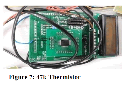
47k Thermistor |
| A thermistor is a type of resistor used to measure temperature changes, relying on the change in its resistance
with changing temperature. Thermistor is a combination of the words thermal and resistor. If we assume that the
relationship between resistance and temperature is linear (i.e. we make a first-order approximation), then we can say that: |
| ΔR = kΔT |
| Where |
| ΔR = change in resistance |
| ΔT = change in temperature |
| k = first-order temperature coefficient of resistance |
| Thermistors can be classified into two types depending on the sign of k. If k is positive, the resistance increases
with increasing temperature, and the device is called a positive temperature coefficient (PTC) thermistor. If k is negative,
the resistance decreases with increasing temperature, and the device is called a negative temperature coefficient (NTC)
thermistor. Resistors that are not thermistors are designed to have the smallest possible k, so that their resistance remains
almost constant over a wide temperature range. |
 |
| Here we are using negative temperature co-efficient in which the resistance value is decreased when the
temperature is increased. |
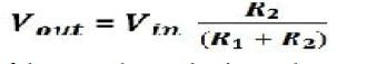 |
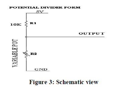
| If the R1 and R2 value is equal means the output is half of the VCC supply. In this circuit output is a variable one. So the
output is depending upon the R2 resistance value. The varying voltage is given to microcontroller. |
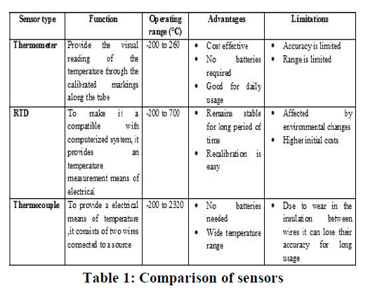
Comparison of sensors |
 |
LEVEL SENSOR |
| Measurement of fluid level is done by help of level sensor. Free flowing substances can be measured by using this
sensor, such as water, oil, slurries, fuel etc. Granular/powder form solids (solids which can flow) also can be measured. It is
classified in different ways depends on kinds. The following figure shows the classification of |
| sensor. This also measured by using potential divider form. In this case level sensor yields minimum output.
Hence it is amplified by using LM741 OP-AMP. Float will depend on the water level. If float varies, then the resistance
will be varied. The output is given to the inverting amplifier LM 741. Amplifier is inverting the output signal and also
amplified. Inverting amplifier inverts from 0 to 180 degree. So the output will be in negative state. That negative signal
voltage is given to next stage of gain amplifier LM 741. This is constructed by another operational amplifier so the output
will be positive signal. In the gain amplifier the variable resistor is connected in the feedback path, by adjusting the resistor
we can get the desired gain. Then the final voltage is given to MSP430. |
HUMIDITY SENSOR |
| Humidity is the measure of water vapor present in a gas. Vapor is a term that refers to the gaseous form of a
substance that normally exists as a solid or liquid. When liquid exists as a gas, it exerts pressure on its surroundings. This
pressure determines the amount of vapor in the air at a given temperature. |
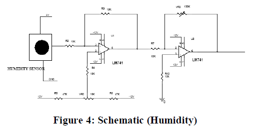 |
| The humidity sensor is consists of astable muliti vibrator in which the capacitance is varied depends on the
humidity level. So the multi vibrator produces the varying pulse signal which is converted into corresponding voltage
signal. The voltage signal is given to inverting input terminal of the comparator. The reference voltage is given to noninverting
input terminal. The comparator is designed by the LM 741 operational amplifier. The comparator is compared
with reference humidity level and delivered the corresponding error voltage at its output which is given to next stage of
gain amplifier in which the variable resistor is connected in the feedback path by adjusting the resistor we can get the
desired gain. Then the final voltage is given to microcontroller or other circuit in order to find the humidity level in the
atmosphere. |
RELAY AND LCD DISPLAY |
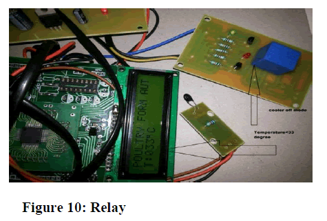
Relay |
| Relay is an electrically operated switch. Current flowing through the coil of the relay creates a magnetic field
which attracts a lever and changes the switch contacts. The coil current can be on or off so relays have two switch positions
and they are double throw (changeover) switches. Relays allow one circuit to switch a second circuit which can be
completely separate from the first. Here it is used for controlling valve, CPU fan and bulb. |
Display |
| A 16x2 LCD display is very basic module and is very commonly used in various devices and circuits. It is used to
display the measured parameters in the poultry farm. |
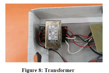
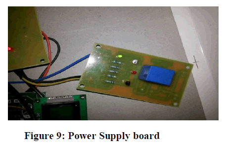
POWER SUPPLY |
| The ac voltage, typically 220V rms, is connected to a transformer, which steps that ac voltage down to the level of
the desired dc output. A diode rectifier then provides a full-wave rectified voltage that is initially filtered by a simple
capacitor filter to produce a dc voltage. This resulting dc voltage usually has some ripple or ac voltage variation. |
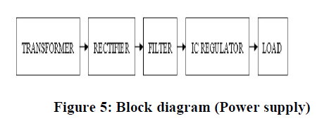 |
| A regulator circuit removes the ripples and also remains the same dc value even if the input dc voltage varies. This
voltage regulation is usually obtained using one of the popular voltage regulator IC units. Here combined supply is used for
elements and OP-AMP (+12,-12). |
IAR WORK BENCH |
| IAR Systems is a Swedish computer software company that offers development tools for embedded system. IAR
Systems was founded in 1983, and is listed on NASDAQ OMX in Stockholm. The coding is written in embedded c and
simulated using this environment. |
RESULTS AND DISCUSSION |
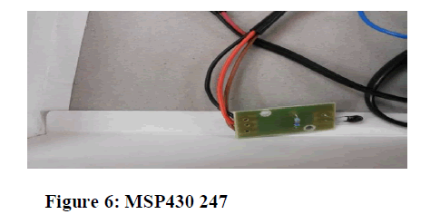
| Initially the MSP430 247 is configured through parallel port with help of work bench. Temperature sensor is tested
for different voltage level with help of voltage divider bias circuit. It is then interfaced to the controller at the channel 6
(PORT 6). |
 |
 |
| Basically the temperature sensor will produce 4 to 20mA current output. In practical without temperature
transmitter the sensor won’t give the output. So it is necessary to interface sensor to controller through transmitter. Here
47k thermistor used for temperature measurement due to cost constraints. Configuration of 47k sensor as
follows,Transformer is used in two different ways. Such that 9V and 15V windings in order to utilize op amp. The ac
voltage is converted in dc voltage with help of rectifier and regulator circuit.Diodes are connected in bridge mode. Two
mode of configuration used specially center tapped. IC 7805 used as 5V regulator and IC 7812 used as 12V regulator. |
 |
 |
| Relay used as output control unit. It is configured in both normally open mode and normally closed mode. |
 |
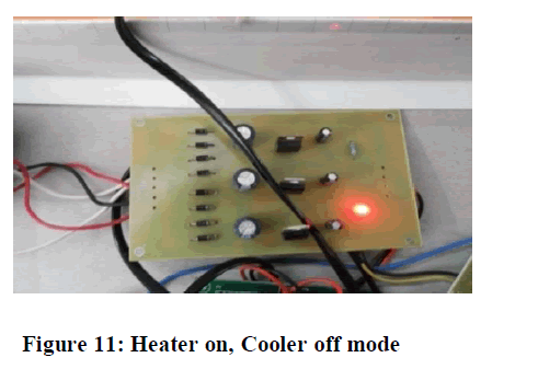 |
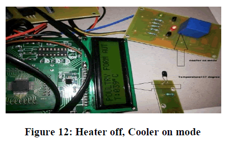
| The temperature of the incubation tray is maintained in particular level. That is 33°C to 37°C. If the level is
exceeds or below the prescribed level then the micro controller will turn on the cooler or heater function. First if the
temperate is below 33°C, then the electric bulb (used for heating purpose) which is activated by relay will be turned on.
Suppose if the tray is over warmed then there is possibility of egg gets damaged. Hence in order to avoid it there is also provision for cooling. If temperature is above 37°C, then the CPU fan (used as cooler) which is activated by
relay will be turned on. |
 |
CONCLUSION |
| The system design for poultry farm automation has been analyzed at different levels. Temperature sensor
especially 47K thermistor is calibrated for different values. Temperature sensor is successfully interfaced to the controller
and tested with different values. CPU fan and electric bulb is interfaced to the relay circuits. Embedded coding is done for
the first level process in C language and simulated by using IAR work bench. Executable file is diffused into the controller
with help of parallel port terminal. |
Future work |
| For the first level of design the temperature and humidity sensors has been interfaced. Further the level sensor will
be analyzed and it will be connected to feedback amplifier then to controller. RTC (Real Time Clock) will be interfaced
soon. Also feed control and tank valve control will be done in order to complete the automation of poultry farm
environment as well as tank model will be done for effective environment. |
References |
- MohdFauzi Othman, KhairunnisaShazali, “Wireless Sensor Network Applications: A Study in Environment Monitoring System,” International Symposium on Robotics and Intelligent Sensors 2012 (IRIS 2012), Procedia Engineering 41 (2012) 1204 – 1210
- ShihongWu,Kunlin Wu, Jian Liang, ZhengmingLi,Ping Yang, “Design of Remote Environment Control System of Intelligent Network Henhouse Based on ARM9,” ELSEVIER Trans, Procedia Engineering 15 (2011) 1056 – 1060.
- N.R.Patel, S.S.Thakare, D.S.Chaudhari “A Review of Different Parameter Monitoring Systems for Increasing Agricultural Yield,” IJITEE Trans ISSN:2278-3075, Volume-2, Issue-4, and March 2013.
- Awati J.S., Patil V.S. AND Awati S.B. “Application of Wireless Sensor Networks for Agriculture Parameters,” International Journal of Agriculture Sciences Trans. ISSN: 0975-3710 & E-ISSN: 0975-9107, Volume 4, Issue 3, 2012, pp-213-215.
- I.S.P. Nagahage, E.A.A. Dilrukshi, “Solar Powered Automated Irrigation System,” ACEPS – 2012.
- M. Dinesh, P. Saravanan, “FPGA Based Real Time Monitoring System for Agricultural Field,” International Journal of Electronics and ComputerScience Engineering ISSN- 2277-1956.
- Jianwei Li, Hong Zhou, Huiqin Li, Yan Li, “Design of Humidity Monitoring System Based on Virtual Instrument,” 2011 International Conference on Advances in Engineering , Procedia Engineering 00 (2011) 000–000.
- Lu Changhua, Wu Zizhi, Wang Lifang. “Establishment and application of computerized production management system for Large scale poultry farm,”[J].Transactions of the CSEA, 2003, 11:256-259.
- TengGuanghui, Cui Yin’an. “Study on the Environment Control Virtual System of Poultry House,” Journal of china agricultural university, 2000,5(2):59-62.
- GopalaKrishnaMoorthy.K, Dr.C.Yaashuwanth, Venkatesh.K, “A Wireless Remote Monitoring Of Agriculture UsingZigbee,” International Journalof Engineering and Innovative Technology (IJEIT) Volume 2, Issue 8, ISSN: 2277-3754, February 2013.
- Iqbal Singh, MeenakshiBansal, “Monitoring Water Level in Agriculture Using Sensor Networks,” International Journal of Soft Computing andEngineering (IJSCE) ISSN: 2231-2307, Volume-1, Issue-5, November 2011.
- Joaquin Gutiérrez, Juan Francisco Villa-Medina, Alejandra Nieto-Garibay, and Miguel Angel Porta-Gándara, “Automated Irrigation System Using aWireless Sensor network and GPRS module”. IEEE Trans.
|