Keywords
|
| PID controller, frequency regulation, wind turbine, rotor speed |
INTRODUCTION
|
| The rapid growth in energy demand and human progresses in various scientific and industrial fields have increased the need to investigate its various resources of energy. To meet the energy demand of all households worldwide, energy supplies must double by 2050 [1]. These facts along with economic problems and the increment of fuel cost have encouraged the researchers in various countries to pay more attention to renewable energies. Therefore, the wind, as one of the renewable energy resources, and its optimal exploitation methods, have been noticed so that the predictions indicate that in 2020 the portion of wind in generating the energy required for human activities will be more than 20%. The design of wind turbines depends on the conditions of the location they are installed, and most of them are designed to generate power with the minimum possible cost at low wind speeds. Thus, if the wind speed exceeds a specified limit, some of the important parts of turbine may be harmed. The designers use various control systems to prevent these harms and also to optimal exploitation of turbines. The most important control systems are stall control, pitch control, and yaw control, among which the pitch control is the most common system [2][3]. |
| Frequency regulation in interconnected networks is one of the main challenges posed by wind turbines in modern power systems. Frequency deviations can cause under/over frequency relaying and disconnect some loads and generations. Frequency regulation becomes a major concern when the system is delivering an isolated or static load [4]. Hence there is a need to regulate the output frequency of wind turbine. Induction generators are commonly used generators in wind turbine. Induction generators are predominantly used due to their rugged and simple construction. Their easy maintenance and over speed capability makes them suitable for wind turbine application [5]. The output frequency of induction generator predominantly depends upon its rotor speed and hence in order to regulate the output frequency the rotor speed needs to be controlled. |
| Investigation of standard and advanced controls of variable speed wind turbine has been done.PI control acting on a measurement of electrical power was the industry standard for constant-speedmachines [6].Most commercial systems are implemented using single input single output (SISO) systems. Advanced controls robust multiple input multiple output (MIMO) method,adaptive or nonlinear techniques have also been reported [11].Variable-speed wind turbines have become more prominent and the blade pitch angle control is the most effective method of controlling the speed and hence the output frequency. |
| In this paper a Proportional Integral Derivative (PID) controller is used to regulate the frequency of the wind turbine by controlling the blade pitch angle. In this paper the complete system is simulated is using Matlab-Simulink package. The performance of the PID controller based system is compared with Linear Quadratic Regulator control scheme. |
LINEARIZED DYNAMIC MODEL [6]
|
| The wind turbine is characterized by no dimensional curves of the power coefficient (Cp) as a function of both the tip speed ratio (λ) and the blade pitch angle (β). Cp can be defined as the electricity produced divided by the total energy available in the wind at that speed and λ is the ratio of the angular rotor speed of the wind turbine to the linear wind speed at the tip of the blades. |
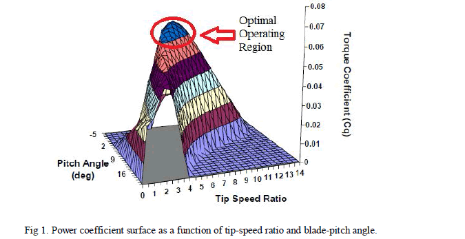 |
| In order to fully utilize the available wind energy, the value of λ should be maintained at its optimum value. An optimum value of λ corresponds to the maximum value of Cp.The fundamental dynamics of the variable-speed wind turbine are captured with the mathematical equation (1). |
 |
| Jtis the moment of inertia of the turbine rotor in kg.m2, ω*t is the angular shaft speed in radians/second ,Tw is the aerodynamic torque in Nm ,Tm is the mechanical torque in Nm necessary to turn the generator and is assumed constant value commanded by the generator. Because the generator moment of inertia of a direct-drive turbine is generally several orders of magnitude less than Jt, it has been neglected. |
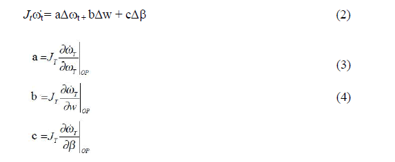
| The equation (1) is linearized by selecting operating pointsWop, ωtop and βop corresponding to wind speed, rotor speed and pitch angle respectively. The operating points are chosen such that the aerodynamic stability of the system is maintained. The linearized model is as shown in equation (2), where a, b and c are the linearization coefficients given by the partial differential of Jtω*t with respect to ωt,w andβrespectively at their respective operating points |
 |
| A. Turbine Model |
| Applying Laplace transform to equation (2) gives |
 |
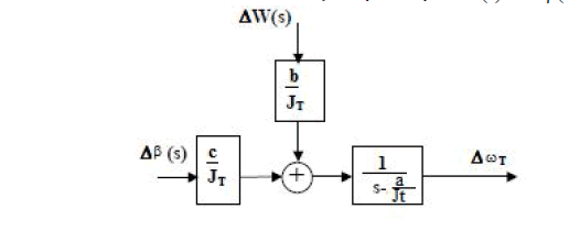 |
| The linear turbine model is as shown in figure (2) where |
| Figure 2.Linear Turbine Model |
| The rotational speed operating point ωtop was selected to be desired constant speed of 600 rpm (62.83 rad/sec), Wop as 13 m/sec [7] and βop as 9 deg. |
| B. Actuator Mode |
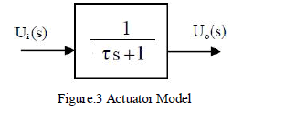
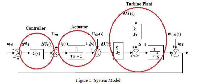
| The pitch actuator can be modeled with a simple first-order model. Blade pitching inertia is very small in comparison with other terms and can be neglected. The actuatortransfer function is described by transfer function as shown in equation (7). |
 |
| The value of time constant τ is taken as 0.20.The block diagram of the actuator model is as shown in figure (2) with input and output as pitch angles Ui(s) and Uo(s) respectively. |
 |
| C. Controller Model |
| A PID controller with input as rotor speed and output as pitch angle was used with the transfer function described as shown in equation (8) with Kp, Ki and Kd as proportional, integral and derivative gains. |
 |
 |
| D. System Model |
| The complete model of the system is obtained as shown in figure (4) consisting of the turbine model, actuator model and the controller model. |
 |
SIMULATION RESULTS
|
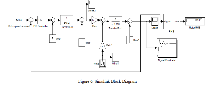
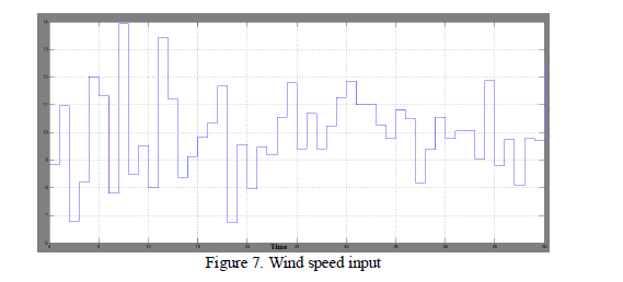
| The system model was simulated using MATLAB Simulink package. The wind speed input was given using a random generator block in Simulink with a mean value of 10m/s and a deviation of 3 m/s. The output of the system ïÃÂ÷t was obtained for the turbulent change in the wind speed. The output of the system was measured in terms of Root Mean Square (RMS) error [8]. RMS error is defined as the fraction of change in RMS value of the output rotor speed to the desired rotor speed of 62.83 m/s. The controller is tuned in order to reduce the RMS error to the least possible value. Manual tuning of controller [9] and design optimization tool in Simulink [10] were the two methods identified and adopted to tune the controller gain to optimum values such that the RMS error is minimized. |
 |
 |
| A.Simulink design optimization toolbox |
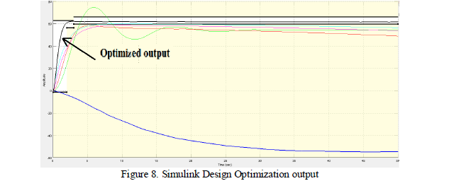
| Simulink Design Optimization improves designs by estimating and tuning model parameters using numerical optimization. The desired response or output rotor speed was specified in the signal constraints toolbox with a peak overshoot of 0% and desired final value of 62.83.Optimization was performed by selecting gradient descent algorithm to arrive at the desired response within 10 iterations. The optimized values of gains were obtained as Kp =43.4186, Ki=- 0.2895 and Kd=30.5946. The RMS value of output speed was 61.85 m/s resulting in an RMS error equal to 1.6%. |
 |
| B. Manual Tuning |
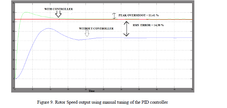
| It was observed that in the absence of the controller the RMS error was as high as 14.38 % (output RMS of 53.79 m/s).The absence of a PID controller resulted in a larger rise time and RMS error. In the absence of derivative and integral gain (P controller), the system has a faster response but the RMS error is high. When a PI controller is used, the system response time increases as compared to a PID controller. The addition of a derivative component improves system response.The controller gainsKp, Ki and Kd were varied over a wide range of values [9] such that the RMS error is minimum. At the gain values of Kp =50, Ki =10 and Kd =40 the rotor speed has 0% RMS error. But a peak overshoot of 11.41 % is observed as shown in figure (9). |
 |
| Manual tuning was observed to be a tedious method as it involves varying the gains over a wide range of values and checking RMS error for each of the variation in gain. It is difficult to obtain an output response with zero RMS error and and least overshoot using manual tuning of controller gains. |
| Hence the goal of minimizing the overshoot and decreasing the RMS error was observed to be conflicting. Manual tuning of PID controller is effective in minimizing the RMS error and the design optimization method is effective in minimizing the overshoot of the output rotor speed. |
COMPARISON WITH LINEAR QUADRATIC REGULATOR (LQR) CONTROL SCHEME
|
| An LQR control scheme is used when the system dynamics is described by linear differential equations and the cost is described by a quadratic function. The PID control was compared with LQR control scheme under nominal and extreme conditions [11]. It was observed that under extreme conditions like cold air, low atmospheric temperature, wind turbulence etc., the rotor speed showed larger variation when operated using PID controller compared to LQR controller. But under nominal conditions i.e. close to the operating point, the PID controller is significantly better than LQR controller. |
| In terms of the cost function [12] of the two controllers, under extreme conditions of cold air and ice accretion on the turbine blades the LQR controller outperforms the PID controller. Such off-design extreme conditions are unidentified by the PID controller. Hence under nominal conditions close to operating point a well-tuned PID controller is the optimum choice to control the rotor speed and hence regulate the output frequency of a wind turbine. |
CONCLUSION
|
| In this paper the output frequency of a wind turbine system driven by an induction generator was regulated by controlling the rotor speed of the generator using a PID controller. The system was simulated using Matlab Simulink software package. The gains of the PID were tuned using manual tuning and design optimization toolbox. The manual tuning of the gains delivered zero RMS error in the output but with a peak overshoot of 11.41 %.Using Simulink design optimization tool the peak overshoot was reduced to zero but there was an RMS error of 1.6 % in the output. The manual tuning method and design optimization method are suitable for minimizing the RMS error and peak overshoot of the output response of the turbine system respectively. The task of simultaneously minimizing RMS error and overshoot was found to be contrasting. The performance of the PID controller was compared to LQR control scheme in terms of rotor speed and cost function and it was concluded that under nominal conditions close to operating points the PID control significantly outperforms the LQR control scheme. |
ACKNOWLEDGEMENT
|
| I would like to thank Prof. V Chayapathy for his valuable advice and suggestions to improve the organization and quality of this paper. Without his persistent guidance this research paper would not have been possible. |
References
|
- “Deciding the Future: Energy Policy Scenarios to 2050 Executive Summary”,World Energy Council ,pp.2,2007.
- Erich Hau, “Wind turbines, fundamentals, technologie , applications, economics”, Springer, IIEdition,pp. 73 – 88, 2005.
- Thomas Ackermann, “Wind power in power system”, John Wiley and Sons, pp. 13-20, 2005.
- H. Bevrani, F.Daneshfar, R. P. Daneshmand, “ Intelligent Power System Frequency Regulations Concerning the Integration of Wind PowerUnits”, Wind Power SystemsGreen Energy and Technology, Volume 0, pp. 407-408, 2010.
- Sathyajith Mathew, "Wind Energy Fundamentals, Resource Analysis and Economics", Springer-Verlag Berlin Heidelberg, 2006.
- Maureen Hand, “Variable-Speed Wind Turbine Controller Systematic Design Methodology: A Comparison of Non-Linear and Linear Model-Based Designs,” NREL Report No. TP-500-25540, National Renewable Energy Laboratory, July,pp. 1-51, 1999.
- “Real time wind and weather report map India”,http://www.windfinder.com/weather-maps/ report/ india#9/ 12.9671/77.5827
- Kendall, L., Balas, M.J., Lee, Y.J., and Fingersh, “Application of Proportional-Integral and Disturbance Accommodating Control to VariablespeedVariable Pitch Horizontal Axis Wind Turbines,” Wind Engineering (12:1), pp. 21-38, 1997.
- Susmita Das,,AyanChakraborty,, Jayanta Kumar Ray,, SoumyenduBhattacharjee,, Dr. BiswarupNeogi, “ Study on Different Tuning Approachwith Incorporation of Simulation Aspect for Z-N (Ziegler-Nichols) Rules”,International Journal of Scientific and Research Publications, Volume 2,Issue 8,pp. 2, 2012 .
- Simulink Design Optimization”,http://www.mathworks.in/ products/sl-design-optimization
- Carlo E.D. Riboldi,“Advanced Control Law for variable speed wind turbine and supporting enabling technologies”, Politecnico di Milano,Department of Aerospace Engineering, 2012.
- C.L. Bottasso, A. Croce, B. Savini, L. Riviello, `Performance Comparison of ControlSchemes for Variable-Speed Pitch-Regulated WindTurbines', The Science of Making Torque from Wind , Journal of Physics: Conference Series 75 , pp. 7-9, 2007.
|