ISSN ONLINE(2278-8875) PRINT (2320-3765)
ISSN ONLINE(2278-8875) PRINT (2320-3765)
Ankita S.Kulkarni1, Priyanka S.Dhayarkar1, Harsha H.Ambure1 and Ashwini S.Shinde2
|
| Related article at Pubmed, Scholar Google |
Visit for more related articles at International Journal of Advanced Research in Electrical, Electronics and Instrumentation Engineering
High tension transformers are critical and expensive components of the power system. These transformers play an important role in power delivery and integrity of the power system network. Due to the long lead time for repair and replacement of the HT transformers, there is a need of transformer protection which limits the damage to the HT transformer.HT Transformers are protected primarily against faults and overloads. The type of protection used, should minimize the time of disconnection for faults within the transformer and to reduce the risk of catastrophic failure to simplify eventual repair. Any extended operation of the transformer under abnormal condition such as faults or overloads compromises the life of the HT transformer, which means adequate protection should be provided for quicker isolation of the HT transformer under such conditions. It is necessary to choose appropriate protective device to ensure safety and reliability of the HT transformer. Circuit protection devices such as Moulded case circuit breaker and Motor protection circuit breaker protect the expensive HT transformer by rapidly disconnecting power to components in the event of abnormal operating condition. The comprehensive transformer protection is provided in this project by protective relays like pressure switch, flow switch, Buccholz relay and sensing the temperature of the HT transformer is done by PT 100 and all this is achieved with the help of digital circuitry in the control panel.
Keywords |
| HT Transformer, Moulded case circuit breaker, Motor protection circuit breaker, pressure switch, flow switch, Buccholz relay and PT 100 |
INTRODUCTION |
| Automation has many benefits like it saves labour, energy, materials and improves quality, accuracy and precision. Two common types of automation are Feedback control and Sequence control. The feedback control is usually continuous and involves taking measurements using sensors and making calculated adjustments to keep the measured variable within a set range, and the other is sequence control, in which a sequence of discrete operations is performed, often based on system logic. A sequential logic may be either a fixed sequence or a logical sequence. Logical sequence control performs various actions depending upon various system states. A sequential control is relay logic by which electrical relays engage electrical contacts which either starts or interrupts power to a device. Thus, we use sequential logic in our project, in which depending upon fault occurred, specific action will be taken. |
| The main idea behind the project is to provide protection to the HT transformer using different functioned relays such as pressure switch, flow switch, Buccholz relay, MCCB and MPCB with the help of a digital control panel. |
| A. Literature Survey: |
| Transformers having electrical current carrying capability of above 33KVA are called high tension transformers. The main concern with HT transformer protection is protecting the transformer against internal faults and ensuring security scheme for external faults. Overloading HT transformers beyond the nameplate rating can cause a rise in temperature of both transformer oil and windings. A HT transformer consists of a set of windings around a magnetic core. The windings are insulated from each other and the core. If the winding temperature rise exceeds the transformer limits, the insulation may deteriorate and may fail prematurely. Prolonged thermal heating weakens the insulation over time, resulting in accelerated transformer loss of life. |
| HT transformer is required for testing of pumps, used in sewage water treatment. If any fault occurs [1] in the HT transformer then the entire testing of pumps is halted. Thus protection of the HT transformer is essential as it may hamper the production. |
| For achieving this goal of protection switches like pressure switch and flow switch are used, circuit breakers like Motor Protection Circuit Breaker[2] and Moulded Case Circuit Breaker are used ,for gas detection, buccholz relay and for monitoring temperature, PT 100 is used. When any of the fault occurs then there is a provision made for audio-visual indication. |
| We have implemented this audio-visual indication of fault condition with the help of digital circuitry. It is possible to implement the fault condition indication with the help of programmable logic controller as well as microcontroller but the disadvantage of both the types of controllers is the cost factor and also need expertise in maintenance. In case of digital logic circuitry it has a longer life with the advantage of low cost and no expert required. |
| B. System specifications: |
| Inputs:- |
| Water circulation flow. |
| Oil circulation flow. |
| Temperature monitoring for transformer. |
| Buchholz Relay. |
| Circuit breakers. |
| Outputs:- |
| Trip |
| Alarm and indication. |
| Transformer specifications:- |
| Frequency- 50Hz |
| Volts at no load- H.V=>6600, L.V=>3300 |
| Amperes- H.V=>219, L.V=>438 |
| Maximum temperature rise in oil- 45 degrees |
EXISTING SYSTEM |
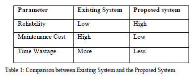
| In the previously existing system protection of the transformer was done manually. A keeper was assigned for looking after the transformer. He had to observe the analog meters indicating the temperature of the transformer .There was no provision to see whether the oil and water flow are present or not. A small ringing bell was placed to indicate the fault in buccholz relay and no protection was provided for indicating the overload condition of the pump. Thus, the previously existing system is completely manual; it is not reliable and does not make efficient use of human labour, energy and materials. |
 |
| The proposed system will consist of a pressure switch which will indicate whether transformer oil is continuously flowing from the conservator to the transformer, keeping temperature of the transformer within specified limit. The temperatures of HT transformer can rise up to 45o C above the room temperature and a PT100 sense this temperature and indicate it on the digital panel meter [3]. There will be flow switch to see if water is continuously flowing so as to cool the hot oil coming out from the transformer. The buccholz relay detects air leaks into the system [1].A Motor Protection circuit breaker is used for protecting the pump from overloading. The pump is used to transport the oil from the transformer to the conservator. A Moulded Case circuit breaker is used to protect the entire control panel from getting damaged [2]. |
 |
| A.Block Diagram: |
 |
Functions: |
Inputs: |
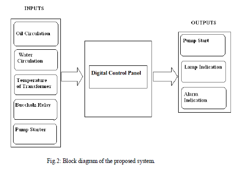
| 1) Oil circulation flow - Oil is used for cooling the transformer hence it is essential that oil circulation flow is maintained with help of pressure switch to avoid transformer from getting over heated. |
| 2) Water Circulation flow - Water is used for cooling the hot transformer oil and hence it is essential that flow of water is maintained with help of flow switch so that continuous cooling of oil occurs. |
| 3) Buchholz Relay - It is a protecting device. It is designed to detect the air leaks into the system which may cause short circuit, arcing, or other dangerous electrical faults, such as an explosion or deteriorating condition of overheating. |
| 4) Temperature Sensor - A temperature sensor PT100 having range of -30 to 200oCis used to continuously monitor the temperature of the transformer so that we can see the current temperature of transformer so as to protect it from overheating. |
| 5) Circuit breaker - Circuit breakers used are MPCB and MCCB. They are automatically operated electrical switches designed to protect an electrical circuit from damage caused by overload and short circuit. Their basic function is detecting a fault condition and interrupts current flow. |
Outputs: |
| Audio-video indication is provided when fault conditions occurs and trips the system from main supply. |
WORKING PRINCIPLE |
| A three phase supply is given to the Moulded case circuit breaker which will protect the entire circuitry from over current. A moulded case circuit breaker is a device designed to isolate a circuit during an over current event without the use of a fusible element. It is a protective device that protects against two types of over current situations; Overload and Short Circuit. |
| The supply then is passed to a contactor. When current passes through the electromagnet of the contactor, a magnetic field is produced; this attracts the moving core of the contactor. The moving contact is propelled by the moving core; the force developed by the electromagnet holds the moving and fixed contacts together. When the contactor coil is deenergized, gravity or a spring returns the electromagnet core to its initial position and opens the contacts. |
| Through contactor the supply goes to the Motor protection circuit board which in turn drives the pump for oil circulation. Motor Protection circuit breaker is a resettable, adjustable current device used for protecting motor from overload condition. To examine whether oil flow is present or not, there is a pressure switch adjusted to 5kg limit. A pressure switch is used to detect the presence of oil pressure when this pressure falls below the set point; the normally closed contacts will become open, giving an audio visual indication. For cooling of oil we have water, to examine whether water flow is present or not, a flow switch adjusted to 3 Litres per minute. If the flow volume through a given system decreases below this limit, it will trigger an alarm giving an audio visual indication. |
| Along with excessesive load current it is also required that, the absolute temperature of the windings and transformer oil remains within specified limits. Hence continuous monitoring of the HT transformer temperature [3] is required which is done by PT100 and displayed on digital panel. The condition that transformer temperature exceeds 45degree Celsius above room temperature is prohibited and if it occurs then audio visual indication will be given. During a fault in an oil-immersed transformer, arcing will occur, releasing gas from decomposition of the oil. The gas passes through the oil pipe to the conservator and can therefore be detected by a buchholz relay. Air is also connected in buchholz relay which originates from air bubbles trapped in the transformer when the transformer was filled with oil.Buchholz relay has a trip device, when there is enough gas or air bubbles in device ,it will given alarm. |
RESULTS |
 |
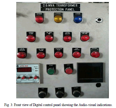
| The fig 3 shows the digital control panel made for protection of the 2500KVA transformer. It shows the various visual indications for various fault conditions. It also provides audio indication for fault condition and a digital panel meter indicating temperature of transformer. |
 |
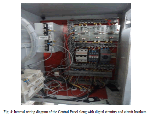
| The fig.4 shows the digital circuitry on the top right, all the system inputs are given to this digital circuitry from bottom and outputs taken from top are given to lamps and hooter.The MCCB,contactor and MPCB are connected in series and SMPS provides 24V to digital circuitry for driving lamps and hooter. |
CONCLUSION |
| HT Transformers play a significant role in power system delivery. Proper application of relay elements that monitor a transformer’s thermal state and through-faults can provide both short and long term benefits. Thus in this paper we have presented that how we can replace human intervention by automatic system of transformer protection using digital circuitry and various protecting devices. |
ACKNOWLEDGEMENT |
| We are thankful to Mrs Ashwini Shinde for providing valuable information and constant encouragement. This work was supported in part by the Wilo Mather Platt. |
References |
|