ISSN ONLINE(2278-8875) PRINT (2320-3765)
ISSN ONLINE(2278-8875) PRINT (2320-3765)
Ganji Jhansi Rani1, Pavan Kumar2
|
| Related article at Pubmed, Scholar Google |
Visit for more related articles at International Journal of Advanced Research in Electrical, Electronics and Instrumentation Engineering
Distributed generation (DG) systems are interfaced with the electrical power network most commonly by means of power electronic converters. This paper deals with a single-phase inverter for DG systems which require improvement in power qualities, such as harmonic elimination and reactive power compensation for grid-connected operation. The main theme of the projects is to integrate the DG system with shunt active power filter capabilities. By using this technique, the inverter controls the active power flow from the renewable energy source to the grid and also performs the nonlinear load current harmonic compensation by keeping the grid current nearly sinusoidal. The power quality control strategy employs a current reference generator based on sinusoidal signal integrator and instantaneous reactive power (IRP) theory together with a dedicated repetitive current controller. Simulation of the power quality control scheme based inverter is carried out for 4-kVA inverter.
Keywords |
| Distributed Power Generation, Single Phase Inverter, Power Quality, Power Conditioning. |
INTRODUCTION |
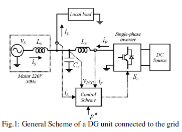
| RECENTLY, due to the high price of oil and the concern for the environment, renewable energy is in the limelight. This scenario has stimulated the development of alternative power sources such as photovoltaic panels, wind turbines and fuel cells [1]–[3]. The distributed generation (DG) concept emerged as a way to integrate different power plants, increasing the DG owner’s reliability, reducing emissions, and providing additional power quality benefits [4]. The cost of the distribution power generation system using the renewable energies is on a falling trend and is expected to fall further as demand and production increase. The energy sources used in DG systems usually have different output characteristics, and for this reason, power electronicconverters are employed to connect these energy sources to the grid, as shown in Fig. 1. The power electronic front-end converter is an inverter whose dc link is fed by an ac/dc converter or by a dc/dc converter, according with the DG source type. The commercial front-end inverters are designed to operate either as grid-connected or in island mode. In grid-connected mode, the voltage at the point of common coupling (PCC) is imposed by the grid; thus, the inverter must be current-controlled. When operated in island mode, the inverters are voltage-controlled, generating the output voltage at a specified amplitude and frequency [5], [6].Coming to the grid-connected mode, almost all the commercial single-phase inverters for DG systems inject only active power to the grid, i.e., the reference current is computed from the reference active power p∗that must be generated [7].It is possible and can be convenient to integrate power quality functions by compensating the reactive power and the current harmonics drawn by specific local nonlinear loads (see Fig. 1). The single-phase inverter can acquire active filtering features just adding to its control software some dedicated blocks that are specific to shunt active power filter (APF).This paper proposes and validates an enhanced power quality control strategy for single-phase inverters used in DG systems. The idea is to integrate the DG unit functions with shunt APF capabilities. With the proposed approach, the inverter controls theactive power flow from the energy source to the grid and also performs the compensation of reactive power and the nonlinear load current harmonics, keeping the grid current almost sinusoidal.The integration of APF capability in single-phase inverters needs a particular attention since the control techniques (for example, to find the reference current) were developed for three phase APFs, and consequently, must be adapted for single-phase systems. The literature presents different solutions to compute the harmonic extraction task for single-phase APFs [8]. The methods are classified in direct and indirect methods in [8]. The direct methods include the Fourier transform method [10], the instantaneous reactive power (IRP) theory [11]–[14] and the synchronous reference frame (SRF) theory [15]. On the other hand, the indirect methods include the use of enhanced phase-locked loop (EPLL) scheme or a controller such as proportional–integral (PI) to find the reference current [8], [9]. |
 |
| Among these solutions, the IRP and the SRF theories are the most addressed ones in the literature [11]. These strategies were originally proposed for three-phase systems, but they can be adapted for single-phase systems due to their effectiveness. In three-phase systems, both IRP and SRF techniques operate in a reference system with two orthogonal axes (αβ for IRP and dqfor SRF). In single-phase systems, since only one-phase variable exists, it is necessary to create one “fictitious” or imaginary variable in which all frequencies are phase-shifted by 90 electrical degrees with respect to the original variable. With this procedure, a system with two orthogonal variables is created from a single variable, allowing the application of the IRP and SRF theories. |
INVERTER CONTROL SCHEME |
| The block diagram of the single-phase inverter control schemewith enhanced power quality features is shown in Fig. 2.The inverter reference current iF is generated by the referencecurrent generator block and the current control is based on arepetitive controller. |
| A. Reference Current Generator: The reference current generation scheme is shown in Fig. 3and can be divided into two parts: the computation of the harmoniccurrent reference ihα and the generation of the fundamentalreference current i∗1 α corresponding to the active and thereactive power to be generated. |
 |
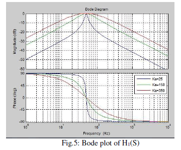
| Generation of the Harmonic Reference Current:The nonlinearload current iLand the PCC voltage VPCC are used tocalculate the reference current for current harmonics compensation.A filter based on SSIs (hereinafter called SSI filter) extractsthe fundamental frequency component ω0 = 2×π×50 (inradian per second) of the load current in stationary αβ frame,as shown in Figs. 3 and 4. The harmonic reference currenti∗hα is obtained from the subtraction of the load current from theoutput of the SSI filter (iL−iL 1α).Generation of the Fundamental Reference Current:Insteadystate operation, the SSI filter shown in Fig. 4 has twosinusoidal states x1 and x2 having the same amplitude and beingphase-shifted by 90 electrical degrees. So, it is possibleto obtain two outputs from a SSI filter, iL1α and iL 1β (whichis always 90âÃâæ shifted respect to iL 1α).This can be seen byanalyzing the two transfer functions of the SSI filter |
 |
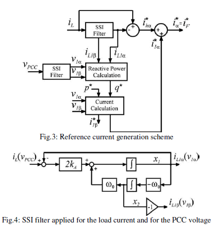 |
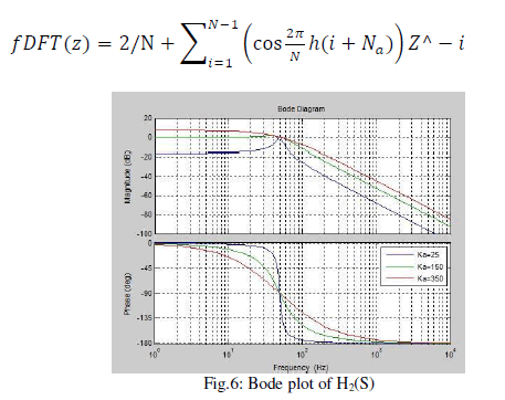
| In steady-state operation, the relationship between the phasesof the transfer functions (1) and (2) in the frequency domain isH1(jω) = H2 (jω) + π/ 2 -(3). The Bode diagrams of (1) and (2) that are shown in Figs. 5and 6 for different values of kaconfirm (3). It is also possibleto see that when kA becomes smaller, the filter becomes moreselective. However, when this happens, the phase delay becomeshigher around the fundamental frequency ω0.Thisproperty is useful for obtaining the orthogonal fundamentalcomponents needed to perform the reactive power compensationof the local load. The signal iL 1β is generated by theSSI only to calculate the fundamental reactive power referenceq∗, using the definition of reactive power from IRP theory as q∗= iL1α v1β − iL1β v1α -(4). To obtain v1α and v1β , another SSI filter is used in the PCCvoltage VPCC by generating v1α and a signal (v1β ) with thesame amplitude and phase-shifted by 90 electrical degrees fromv1α , as shown in Fig. 4. The use of an SSI filter in the PCCvoltage makes the reference current generator insensitive to gridvoltage distortions. The fundamental components of the inverterreference current i∗1α and i∗1β are calculated by imposing thereference power p∗equal to the amount of active power to beinjected into the grid, as follows: |
 |
 |
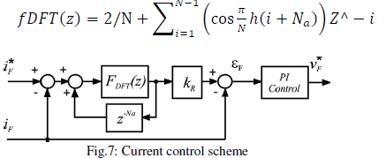
| B. Current Control: For inverters that generate active power and also compensatethe reactive power, the reference current is sinusoidal at fundamentalfrequency, so the use of conventional PI controllers would probably suffice if theirbandwidth is high enough. If theinverter must also compensate the current harmonics, the referencecurrent willbecome non-sinusoidal. In this case, achievingzero –steady-state error is not possible with PI controllers, unlessparticular control schemes are employed.The adopted current control scheme is shown in Fig. 7 and isbased on a repetitive controller along a conventional PI regulatorin order to achieve zero steady-state error when the referencecurrent has a high harmonic content. This scheme has beenoriginally proposed infor shunt APFs, and for this reason,it is also suitable for inverters used for active power generationand having power quality features.Coming to the scheme in Fig. 7, the key issue is the implementationof the repetitive control scheme. The repetitivecontroller is nothing else than an FIR filter of N taps. The filtercan be designed by using the discrete Fourier transform (DFT)toachieve unity gain for every single harmonic to becompensated.As described in detail in, the filter coefficients canbe computed as |
 |
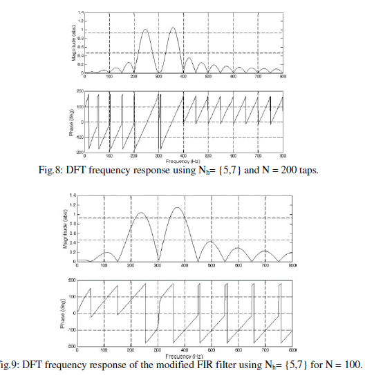
| WhereNis the number of the coefficients,Nhis the set of selectedharmonic frequencies, and Na is the number of leading stepsnecessary to maintain the system stability. The kRparameterfrom Fig. 7 influences the repetitive controller speed response.The number of FIR filter taps is directly related to the samplingfrequency. To implement (6) with a sampling period Tsof 100 μs, we will need an FIR filter by using 200 taps. Forexample, the frequency plots of the FIR filter (6) tuned for thefifth and the seventh harmonics (Nh= 5,7) and implementedwith N = 200 taps are shown in Fig. 8.The implementation of the original repetitive controllerrequires a high number of the filter taps that are necessary for thechosen sampling frequency of 10 kHz. To reduce the taps number,a modified repetitive controller is proposed in this paper.The proposed filter coefficients are computed by using (7). With respect to (6), the proposed filter (7) allows halving thenumber of taps for the same sampling frequency. For a samplingfrequency of 10 kHz, (7) will lead to N = 100 taps with respectto N=200 taps imposed by (6), making the proposed filter moresuitable for Matlab implementation since the computational timewill be significantly reduced. The frequency plots of the proposed FIR filter (7) tuned for thefifth and the seventh harmonics (Nh=5 and 7) and simulatedwith N = 100 taps are shown in Fig. 9. As can be noted fromFig. 9, the proposed FIR filter exhibits similar filtering propertieswith the original filter presented in, but the simulationis simpler due to the halved number of taps. |
 |
 |
SIMULATIONRESULTS |
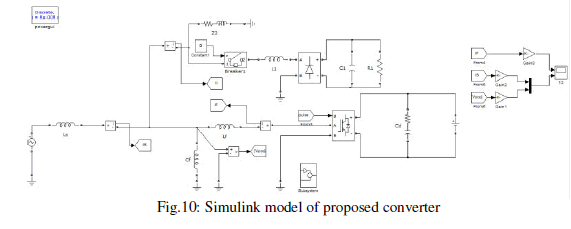
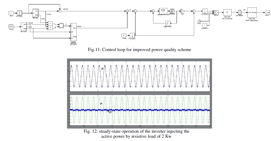
| The general diagram of the Matlab simulation setup is shown inFig. 10, where the positive polarities for grid current iS, loadcurrent iL , and inverter current iFare emphasized, in agreementwith Fig. 1. A general view of the simulation is presented in Fig. 11 and the system parameters are given inTable I. A 4-kVA single-phase full-bridge inverter prototypeusing a switching frequency of 10 kHz has been used for thesimulation results.The simulation platform used to implement the inverter controlsystem based onthe Simulink Matlab 2009B version. The current controller parameters are kR= 1, N= 100 (sampling frequency = 10 kHz), Nh= 2n−1 with n =1,. . .,13, and Na = 2. The PI current controller parameters arekp= 3 and ki= 500.The quantities measured from the system are the invertercurrent iF, the PCC voltage VPCC, and the local load current iL ,as shown in Fig. 10. As the paper focus is on the grid-connectedinverter, the dc energy source has been emulated with a threephasediode rectifier fed by a three-phase variance.The single-phase inverter injects active power into the gridand compensates the harmonics generated by a local load, whichcontains two parts: a 2-kW linear load and a 3-kVA nonlinearcapacitive load (a single-phase diode rectifier with capacitive dcload). |
 |
 |
A. Validation of Active Power Generation: |
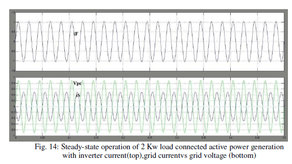
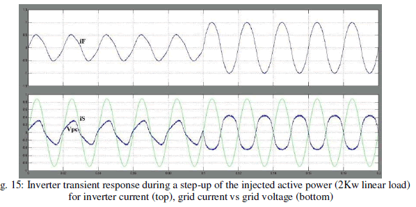
| This test has been performed with the inverter having onlya 2-kW resistive local load. The steady-state operation for theinverter, injecting 2 kW of active power, is shown in Fig. 12. Inthis case, it can be seen that the grid current iSis almost zerobecause the local load power request is completely supplied bythe inverter (iS= iL−iFin Fig. 10). The steadystate operation of the inverter, injecting 3 kW ofactive power, is presented in Fig. 13. It can be seen that the gridcurrent is out of phase with respect to the PCC voltage by 180electrical degrees, which means active power generation. Theinverter current waveform and its Fourier analysis that are alsoillustrated in Fig. 13 show that the injected current is almostsinusoidal. The grid current total harmonic distortion (THD)value was about 2%. |
B. Validation of Current Harmonics Compensation: |
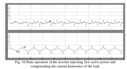
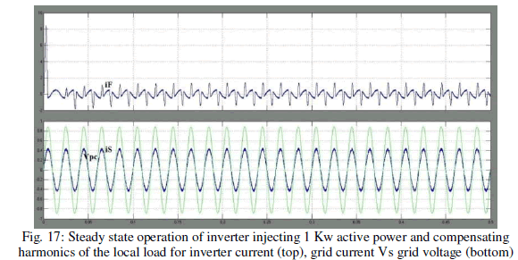
| This test has been performed with the inverter having a localload consisted of the resistance R2 and the diode rectifier. This happens because the inverter-injectedactive power of 1 kWis smaller than the active power requestedby the local load.Thesteady-state operation of the inverter, injecting 1 kW of activepower and compensating the current harmonics of the local load,is shown in Figs. 15 and 16. The inverter current iF, the PCCvoltage VPCC, and the local load current iL are shown in Fig. 15,while Fig. 16 contains the inverter current iF, the PCC voltage VPCC, the grid current iS, and the Fourier analysis of the invertercurrent iF. It can be seen from Figs. 15 and 16 that even if thelocal load current is highly distorted, the mains current is almostsinusoidal. |
 |
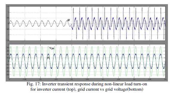
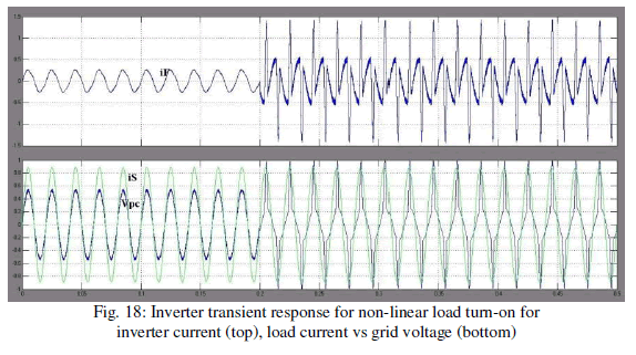
| Also, it can be noted that the grid current is in phase withthe PCC voltage, so in this case, the local load still draws activepower from the grid.The inverter dynamic performance has been evaluated byturning on the load diode rectifier, as shown in Figs. 17 and 18. |
 |
C. Validation of Reactive Power Compensation: |
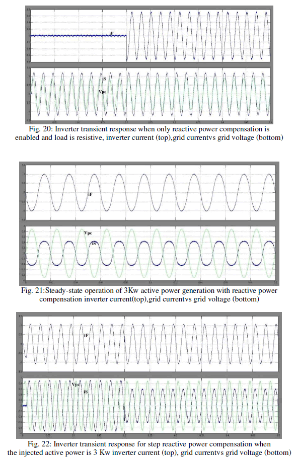
| To clearly emphasize the inverter capability to compensate thelocal load reactive power, the inverter has been operated onlywith an RL load obtained as the series connection between theresistance R2 and the inductance L2 (Table I). The load currentlags the load voltage by about 20 electrical degrees, as shownin Fig. 19.The inverter transient operation obtained for zero active powergeneration when the reactive power is enabled in a step fashionis shown in Fig. 20. |
 |
| The steady-state operation of the inverter, injecting 3 kW ofactive power and compensating the entire load reactive power, isshown in Fig. 21. |
 |
| The grid current is out of phase with respect tothe PCC voltage by 180 electrical degrees, which means activepower generation since the inverter generates more active powerthan the active power requested by the load. |
 |
| Finally, the transient response for step reactive power compensationwhen the generated active power was 3 kW is illustratedin Fig. 22, showing a time response of less than one gridperiod and no particular problems during the transient. |
 |
 |
CONCLUSION |
| This paper deals with a single-phase H-bridge inverter forDG systems, requiring power quality features as harmonic andreactive power compensation for grid-connected operation. Theproposed control scheme employs a current reference generatorbased on SSI and IRP theory, together with a dedicatedrepetitive current controller. The gridconnected single-phaseH-bridge inverter injects active power into the grid and is ableto compensate the local load reactive power andalso the localload current harmonics. Simulation results have been obtained on a 4-kVA inverter Matlabmodel tested for different operating conditions, includingactive power generation, load reactive power compensation,and load current harmonic compensation. The simulation results have shown good transient and steadystateperformance in terms of grid current THD and transientresponse.The integration of power quality features has the drawbackthat the inverter will also deliver the harmonic compensationcurrent with the direct consequence of increase the inverteroverall current and cost. A current limitation strategyshould be implemented and if the inverter output current exceedsthe switch rating, then the supplied harmonic currentmust be reduced. In this way, the inverter available current ismainly used for active power injection and if there is somecurrent margin, this can be used for the compensation of reactivepower and nonlinear load current harmonics. An analysisof the inverter design that takes into account the currentrequired for reactive power and current harmonics compensationis beyond the paper scope and it will be subject of futurestudy. |
References |
|