International Journal of Advanced Research in Electrical, Electronics and Instrumentation Engineering
ISSN ONLINE(2278-8875) PRINT (2320-3765)
ISSN ONLINE(2278-8875) PRINT (2320-3765)
| V. M. Ramaa Priyaa, Amit Kumar Singh Dept. of E&I, Bharath University,Chennai-600073, India |
| Related article at Pubmed, Scholar Google |
Visit for more related articles at International Journal of Advanced Research in Electrical, Electronics and Instrumentation Engineering
Solar energy is by far among the best sources of energy from every perspective. But harvesting solar energy efficiently is not very easy because of the fact that the relative to the earth the sun is moving. The solar panels are mounted they are fixed in some direction, hence they can give maximum output only for the duration when the sun is directly perpendicular to them. This project is an attempt for providing a solution to the above problem. Using this project ths solar panels can be maintained perpendicular to the sun for almost the entire day. For achieving this, the need is to tilt the solar panel in the direction of motion of the sun. For this first the position of the sun is to be sensed then the panel is to be titled in that direction.
INDEX TERMS |
| LAP View, Microcontroller, MPLAB, Motor Driver, Optical Sensor, Solar Panel, Virtual Instrument. |
INTRODUCTION |
| We have a lot of source of energy which we are using regularly for our daily use. We are using maximum number of resources which is non-renewable. These sources cannot be retained. One day it will be finished. Sun is one of the most important sources of energy in the entire world and it is never going to finished. By the solar panel we can generate energy from the sun directly and that type of energy produced by sun is called solar energy. |
| Solar energy is by far among the best sources of energy form every perspective. We should use more and more solar energy as it possible for our energy requirement. But harvesting solar energy eficiently is not very easy because of the fact that the relative to the earth the sun is moving. The solar panels can give maximum power output when only the sun is directly perpendicular to then. |
| By this project we are providing a solution of problem maintain above. By this the solar panels can be maintained perpendicular to the sun for almost the entire day. For achieving this, the need to be sensed the direction of the sun and then the panel is to be tilted in that direction. |
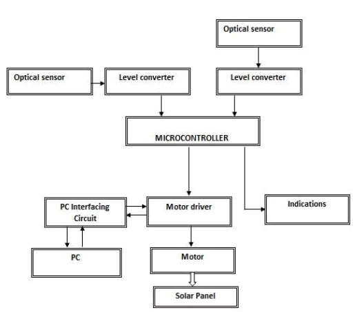
| For sensing the direction of the sun phototransistors are mounted on the both sides in the middle of perpendicular to eachother frame carrying the solar panel. The output voltage is given to the signal conditioning circuit which converts the signals to digital signals which can be given as an input to the microcontroller. |
| The microcontroller gets the input from the signal conditioning circuit and calculates the position of the sun. It then passes appropriate signals to the DC motor drive circuit for moving the panel in the direction of the sun. Also the microcontroller gives the signals to the PC through a PC interface circuit. The PC receivers the data and displays the position of the solar panel on a virtual instrumentation interraces. A DC motor is used in this project for its high accuracy and easy of control. |
PROPOSED SYSTEM |
| 1) In the proposed system renewable energy resources like sunlight is used for generating electricity. |
| 2) It is in turn converted to AC and has been given to the load. |
| 3) Voltage can be measured. |
| 4) The solar panels can be maintained perpendicular to the sun for almost the entire day. |
BLOCK DIAGRAM |
 |
HARDWARE COMPONENTS |
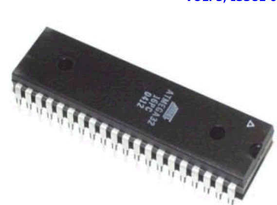
4.1 MICROCONTROLLER-PIC(18LF45K22 I/P) |
| A microcontroller is a small computer on a single integrated circuit containing a processor core, memory and programmable input/ output peripherals. |
| Microcontrollers are used in automatically controlled products and devices, such as automobile engine control systems, implantable medical devices, remote controls, printing, office machines, appliances, power tools, toys and other embedded systems. It is main used in the process which is regular. It used in continues type of process. By the help of microcontroller we are reducing our effort and getting more and more work output easily. |
| There is a program memory in the form of NOR flash or OTP ROM is also often included on chip, as well as a typically small amount of RAM. Microcontrollers are designed for embedded applications, in contrast to the microprocessors used in personal computers or other general purpose applications. |
| Now a day we are developing Microcontroller day by day. By reducing size and cost compared to a design that uses a seprate microcontrollers, memory, and input/output devices, microcontrollers make it economical to digitally control even more devices and processes. Mixed singal autocontroller are common, integrating anaog coponents needed to control non-digital electronic systems. |
 |
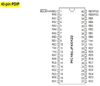 |
| For this project we are using a 40-pin PIC18LF45K22 Microcontroller which is a PIC type Microcontroller. PIC is a family of modified Harvard architecture microcontrollers made by Microchip Technology, derived from the PIC1650 originally developed by General Instrument’s Microelectronics Division. The name PIC initially referred to “Peripheral Interface Controller”. |
| PICs Microcontroller are popular with both industrial developers and hobbyists alike due to their low cost, wide availability of low cost or free development tools, and serial programming (and re-programming with flash memory) capability. They are also commonly used in educational programming as they often come with the easy to use ‘pic logicator’ software. The PIC microcontroller has peripheral features like inbuilt ADC, required to get the signals from the various sensors. Maximum clock frequency is 48MHz and hence faster than 8051. Based on RISC and Harvard architecture and hence even more faster. Embedded C is used for programming the microcontroller. |
4.2 SOLAR PANEL |
 |
| Solar energy can be obtained directly from the sun with the help of solar cell. A solar cell is a packaged, connected assembly of photovoltaic cells. The solar cells use light energy (photons) from the sun to generate electricity through the photovoltaic effect. Solar panel is a group of solar cells. The solar panel can be used as a component of a larger photovoltaic system to generate and supply electricity in commercial and residential applications. Each panel is rated by its DC output power under standard test conditions, and typically ranges from 100 to 320 watts. A photovoltaic system typically includes an array of solar panels, an inverter, and sometimes a battery and or solar tracker and interconnection wining. |
THEORY AND CONSTRUCTION OF SOLAR CELL |
| Solar panels use light energy from the sun to generate electricity through the photovoltaic effect. The majority of modules use wafer-based crystalline silicon cells or thin-film cells based on cadmium telluride or silicon. Silicon is the largest percentage in terms of availability element on the earth. And it doesn’t produce any harm due to usage and as well as processing. The structural (load carrying) member of a module can either be the top layer or the back layer. Cells must also be protected from mechanical damage and moisture. Most solar panels are rigid, but semi-flexible ones are available, based on thin-film cells. These early solar panels were first used in space in 1958. |
| Electrical connections are made in series to achieve a desired output voltage and/or in parallel to provide a desired current capability. The conducting wires that take the current off the panels may contain silver, copper or other non-magnetic conductive transition metals. The cells must be connected electrically to one another and to therest of the system. Extemally, popular terrestrial usage photovoltaic panels use MC3 or MC4 connectors to facilitate easy weatherproof connections to the rest of the system. |
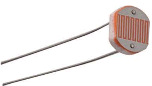
4.3 OPTICAL SENSOR-LDR |
 |
| One of the features of an optical sensor is its ability to measure the changes from one or more light beams. This change is most often based around alterations to the intensity of the light. When a phase change occurs, the light sensor acts as a photoelectric trigger, either increasing or decresing the electrical output, depending on the type of sensor. |
| Optical sensors can work either on the single point method or through a distribution of points. With the single point method, a sole phase changes is needed to activate the sensor. In terms of the distribution concept, the sensor is reactive along a long series of sensors or single fiber-optic array. |
| LDR is used as a light sensor in this project. A light depedent resistor (LDR) or photoresistor is a resistor whose resistance decreases with increasing incident light intensity; in other words, it exhibits photoconductivity. A photoresistor is made of a high resistance semiconductor. If light falling on the device is of high enough frequency, photons absorbed by the semiconductor give, bound electrons enough energy to jump into the conduction band. The resulting free electron (and its hole partner) conduct electricity, thereby lowering resistance. |
| A photoelectric device can be either intrinsic or extrinsic. An intrinsic semiconductor has its own charge carriers and is not an efficient semiconductor, for example, silicon. In intrinsic devices the only available electrons are in the valence band, and hence the photon must have enough energy to excite the electron across the entire band gap. Extrinsic devices have impurities, also called dopants, and added whose ground state energy is closer to the conduction band; since the electrons do not have as far to jump, lower energy photons (that is, longer wavelengths and lower frequencies) are sufficient to trigger the device. If a sample of silicon has some of its atoms replaced by phosphorus atoms (impurities), there will be extra electrons available for conduction. This is an example of an extrinsic semiconductor. Photoresistors are basically photocells. |
4.4 MOTOR |
| Motor is a electrical device which converts the electrical energy into mechanical energy. Here we are using a DC Motor by which we controlled the solar panel by rotating it with the help of DC Motor. |
CHARACTERISTICS OF DC MOTOR FOR OUR PROJECT |
| 4.4.1 TYPE - Permanent Magnet mini DC Motor |
| 4.4.2 VOLTAGE- 5V continuous |
| 4.4.3 CURRENT- 110mA |
| 4.4.4 RPM - 1500RPM |
| 4.4.5 GEARS - Nil |
4.5 MOTOR DRIVER |
| In this project we are using DC Motor but a DC Motor cannot be interfaced to the microcontroller directly because it requires much higher voltage and current. Motor drive is used for this. It is built using npn voltage transistor – BC547. It acts as a interefacing device to supply required power to the motor. DC motors have polarity and direction of rotation depends on direction of current. |
4.6 VOLATAGE MEASUREMENT |
| Since in this project involves only DC power, so measuring the voltage is relatively simple. |
| The voltage can be measured using potential divider circuit. It will be analog signals and can be given to the ADC of the controller. |
SOFTWARE TOOLS |
5.1 MPLAB IDE |
| MPLAB IDE is a software program that is used to develop applications for Microchip microcontrollers and digital signal controllers. This development tool is called Integrated Development Environment or IDE because it provides a single integrated “environment” to develop code for embedded microcontrollers. We used to write the program in C or C++. MPLAB Integrated Development Environment is a free integrated toolset for the development of embedded applications employing Microchip’s PIC and dsPIC microcontrollers. MPLAB IDE runs as a 32-bit application on MS Windows is easy to use and includes a host of free software components for fast application development and super-charged debugging. MPLAB IDE also serves as a single, unified graphical user interface for additional Microchip and third party software and hardware development tools. Moving between tools in a snap, and upgrading from the free software simulator to hardware debug and programming tools is done in a flash because MPLAB IDE has the same user interface for all tools. |
5.2 ORCAD |
| OrCAD is a used to design the circuit. It is an EDA (electronic design automation) software that combines different tools for various stages of a electronic circuit design. OrCAD has a tools for schematic design, PCB design and also simulation tools when the simulation models are available. |
5.3 EAGLE |
| A schematic or a circuit diagram is only a technical representation of a circuit design. However for actually constructing a circuit design into a physical board a PCB (Printed Circuit Board) is needed. A PCB is the base on which the different components are placed and soldered. The PCB contains copper traces or tracks that establish connection between the components placed on the board. The following picture shows a just a PCB and a PC with componets placed and soldered in it. |
 |
| Before a PCB can be physically fabricated it has to be decide where all the components will be placed and arranged and how the PCB traces will connect the different components. This process is colled PCB design. |
| There are different software available that can be used for PCB design. EAGLE (Easily Applicable Graphical Layout Editor) is one such software created by the company called CADSOFT. EAGLE is a easy to use yet very capable software for PCB design. Hence it is the ideal choice for small to medium projects including stident projects. |
5.4 LABVIEW |
| Labview is used for user interface display. LabVIEW (Laboratory Virtual Instrumentation Engineering Workbench) is a platform and development environment for a visual programming language from National Instruments. The graphical language is named “G”. Originally released for the Apple Macintosh in 1986, LabVIEW is commonly used for data acquisition, instrument control, and industrial automation on a variety of platforms including Microsoft Windows, various flavors of UNIX, Linux, and Mac OS. |
WORKING PROCESS |
| We are using a solar panel in this project. For sensing the direction of the sun two phototransistors are mounted on both side of the frame carrying solar panel. The output voltage from these photo transistors will vary depending upon the direction of the sun. This voltage is given to the signal conditioning circuit which converts the signals to digital signals which can be given as an input to the microcontroller. |
| The microcontroller gets the input from the signal conditioning circuit and calculates the position of the sun. It then passes appropriate signals to the motor drive circuit for moving the panel in the direction of the sun. Also the microcontroller gives the signals to the PC through a PC interface circuit. The PC receives the data and displays the position of the solar panel on a virtual instrumentation interface. A DC motor is used in this project for its high accuracy and ease of control. |
CONCLUSION |
| So by the use of this project we can extracts maximum power from the solar panel. By this we can easily save our solar energy. We can increase our efficiency and power of solar energy by using this solar tracker. We can use this type of instruents in the entire field because if we are going to use our non-renewable energy source again and again so one day it will be finished. So we should use our renewable energy sources as much as possible. And this type of project is very useful to hep us to extract 100% output of energy. |
ACKNOWLEDGMENT |
| The author gratefully acknowledges the Faculty of Electronics and Instrumentation Engineering, Bharath Institute of Science and Technology for giving the suppork in this work. |
References |
|