ISSN ONLINE(2320-9801) PRINT (2320-9798)
ISSN ONLINE(2320-9801) PRINT (2320-9798)
Ramya P, Sowbakkiyam S
|
| Related article at Pubmed, Scholar Google |
Visit for more related articles at International Journal of Innovative Research in Computer and Communication Engineering
There are different types of antennas available for various wireless applications. A fractal antenna uses self-similar design in its different iterations to achieve multiband that can receive or transmit electromagnetic radiation within a given total surface area or volume. And it reduces the conductor placement by etching circular from triangular and vice versa, this proposed antenna design can be used in 2.4 GHz(ISM band applications) and LTE systems. In Wireless communications antennas plays a major role to direct the field in particular directions.. This paper also presents the detail step of designing sierpinsky fractal antenna and its structure to improve the return loss, gain, directivity is obtained .ADS software is used for designing of antenna
KEYWORDS |
| LTE, Sierpinsky fractal, ISM band applications, Maxwell’s equation, coupling patches |
I. INTRODUCTION |
| A. Structure Description: |
| Among the fractal types, Koch curve, sierpinsky gasket and carpet has variety of applications of operating in multiband. It has a wide application in the design of miniaturized patch antenna due to its unique self-similarity nature and to make a compact antenna with more conductivity can be achieved using this fractal structure. Under the expanding need of size reduction in Antenna design with low profile, fractal theory can help to provide a great number of solutions for miniaturized antenna |
| B. Fractal with Coupling Patches: |
| Proposed antenna design in normal fractal structure eliminates most of the conducting part of the element which reduces the excitation from feeding point to upper part of the antenna .That will not provide more amount of radiation i.e. the given power do not propagates through the end of the antenna due to its poor coupling .so the coupling patches are used to connect outer triangle to inner triangle in its structure. |
II. RELATED WORK |
| Designers always used to design antenna with different structures [1], [3] and getting the different values of return loss .And there is a change in feeding technique to improve radiation and reducing or getting side lobes for certain applications this may be designed using array as well as MIMO antennas to obtain multiband operations .by changing the substrate thickness and feeding point there will be a change in simulation results. Then the antenna compactness is increasing demand among customers |
| Omar M. Khan, Zain U. Islam, Imran Rashid proposed antenna uses pentagonal shape for the basic fractalization combined with inner sides etched with Koch fractal pattern of the first iteration providing reduction in the overall size of the antenna. For higher order of iterations, more size reduction is achieved, producing equal number of radiation bands. Optimization is done for achieving radiations in the S, C and X bands [4] |
| Abdelati Reha, Ahmed Oulad proposed a two tri-band fractal antennas are studied for the Radio Frequency Identification (RFID) applications using the Method of Moment (MoM). In this reader antenna operating at 289 MHz and 8.12 GHz. The tag antenna exhibits a −10 dB bandwidth of 165 MHz at 3.94 GHz, 149 MHz at 5.65 GHz, and 166 MHz at 8.2 GHz. The maxi-mum read range obtained by the reader antenna is 74.72 cm, and 83.83 cm by the tag antenna [5] |
| Sudhanshu Verma, Preetam Kumar proposed Printed Multiband Minkowski Fractal Curved Antenna The probe fed Minkowski fractal curved antenna is designed with FR-4 substrate forGSM900/1710/GPS1227/1575/WiMAX2500 and IEEE802.11b standard applications. Between the Minkowski fractal curved radiating patch and the ground plane is a foam substrate of thickness 5 mm [6] |
| Ntawangaheza jean de Dieu,wenbiao Zhou proposed Koch based CPW feed dual UWB antenna the first band covers various mobile communication services such as DCS, IMT-2000, UMTS, WLAN, GPS, 3G, 4G, LTE and the second one finds its application in UWB and satellite applications. It is a complex antenna structure because its ground plane also to be designed [9] |
| Jen-Yea Jan and Jia-WeiSu Proposed bandwidth enhancement of a printed wide-slot antenna with a rotated slot. This new model is applied to antennas with a single Micro strip feed line. Due to its numerical efficiency, this model is extremely well suited for design purposes. The model has a very broad range of validity in terms of patch aspect ratio (W/L), substrate dielectric constant (εr) and substrate electrical thickness (h/λ0). However, some physical effects are still neglected by the model, such as the excitation of substrate waves, the mutual coupling with neighboring elements, and the diffraction at the substrate and ground plane edges [10] |
III. PROPOSED ANTENNA DESIGN |
| Sierpinsky carpet with third iteration is designed for the dual band frequency of operation. Antenna can be fed by different feeding technique such as micro strip line feeding, inset feeding, coaxial feeding, proximity coupling feeding and aperture couple feeding. Proposed antenna design uses coaxial feeding with some impedance matching at dual band frequencies. |
| C. Substrate material: |
| FR4 is the fire retardant dielectric material with permittivity of 4.4 and loss tangent of 0.0022 and the thickness is 1.6mm.this material of substrate is chosen because of its low cost and low profile can exhibit good radiation of patch or antenna conductor. |
| D. Design procedure: |
| Proposed antenna design frequency is 2.4GHz |
 |
 |
| E. Layouts in Ads Software |
| The total structure is simulated using ADS 2013 layout simulation. when the design is done in millimeter layout it does the simulation process through meshing .Method of Momentum which solves Maxwell’s differential equation to get the necessary electric as well as magnetic field components and radiation pattern for further analysis of performances. |
| The simulations are carried out using four different meshes: two generated by commercial application (Ansoft Designer), and two by a custom meshed (CGSM). For each mesh generator, 10 or 15 cells per wavelength are used |
IV. SIMULATION RESULTS AND DISCUSSION |
 |
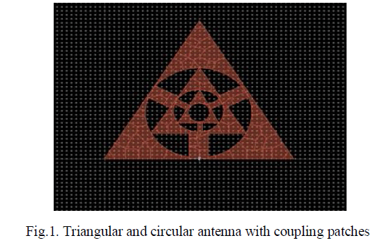
| The above structure is third iteration of sierpinsky carpet with coupling patches from every outside circle to inside triangle. Coupling patches are used to make the antenna to work with perfect matching of the port while inserting into the particular device of operation. Meshing is generated for different structures through method of momentum and infinite element method this may solve the field equations in differential or integral form to obtain electric and magnetic field in phi as well as theta directions |
| The geometry of the proposed antenna has been shown in Fig.1. The fractal antenna with coupling patches is used to improve conductivity. The design process begins with the radiating patch with substrate, ground plane and a feed line. It is printed on a 1.6mm thick FR4 substrate that contains dielectric loss tangent 0.0022, relative permittivity 4.6, and relative permeability with 1. |
 |
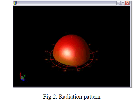
| Radiation pattern is like a Omni directional pattern and it can be used for all directional reception and transmission of signal. This has more coverage throughout the area of propagation. |
 |
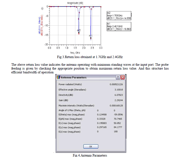
| From the above Gain defines how much power radiated for the applying input power and the directivity defines how efficiently the radiated power will be at given direction with respect to other direction. |
V.CONCLUSION |
| In this paper triangle and circular sierpinsky carpet designed with coupling patches for improving the radiation. This structure eliminates mutual coupling by creating reactive loading. Proposed antenna operates at two different frequencies of 1.7GHz and 2.4MHz with reduced return loss value shows perfect matching. The structure can be changed to get high gain and directivity at the same time by implementing more iterations we can achieve more than two band of operation. |
References |
|