ISSN ONLINE(2320-9801) PRINT (2320-9798)
ISSN ONLINE(2320-9801) PRINT (2320-9798)
| Bhavin Patel1 PG Student, Dept. of VLSI and Embedded Systems, U. V. Patel College of Engineering, Ahmedabad, India |
| Related article at Pubmed, Scholar Google |
Visit for more related articles at International Journal of Innovative Research in Computer and Communication Engineering
Managing Generic IP verification requires consideration of uncertainties & dynamic changes of standard & specification during project execution. Such scenario requires well defined process which needs to be followed throughout the project execution. A creative approach is required to make sure verification architecture is flexible enough to adapt majority of the run time changes enabling faster turnaround time. This article demonstrates guidelines based on real experience to tackle dynamics in Verification.
Keywords |
| Intellectual Property, Universal Verification Methodology, Physical Interface |
INTRODUCTION |
| Generic IP may have multiple protocols support. It can be used with different industry standards of PHYs. It may have wide range of frequency of operation with multiple clocks. It may have multiple interface support for register configuration. It may contain number of timers to come out from Hazards condition. Generic IP may have functionality to disable hardware interrupt as well as software interrupts. Verification approach towards evolving Generic Design IP is discussed in detail which includes general processes and practices followed along with special considerations for managing dynamics. |
VERIFICATION FLOW |
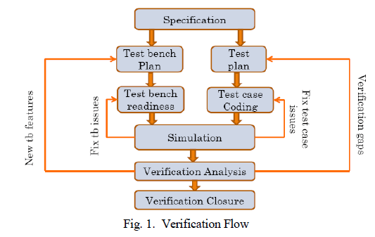
| Major Verification tasks include Verify, report bugs, get bug fixes, verify & evaluate the coverage of verification as shown in Figure 1.Number of iteration determines the time taken to close verification.Verification is less about tools and more about verification engineers’ approach.Quality of verification depends upon: |
| The quality of test plan |
| The quality of test bench environment |
| Effective way of test plan execution |
| A. Verification Plan |
| Verification Plan specifies how design will be verified (Approach), what will be verified (Features) and Sign-off criteria (Checks). Verification test plan must be review with architect, designer & verification engineer. So that will improve the quality of verification plan and also some design/architecture issues might be caught during the review. |
 |
B. Feature Extraction |
| It is very important to digest the Design Spec. and find out different features supported by Design IP to have an brief idea about the use cases. Mainly feature extraction can be done on following parameters: |
| Different functionality in design |
| Basic Functionality |
| Configurations |
| Concurrent functionality |
| Cross verification of configuration/functionality |
| Error conditions |
| Stress conditions |
| Use case scenarios |
| Negative scenarios for security features |
| Corner case scenarios (known/unknown) |
| Multiple the frequencies/baud rate supported by the module |
| All type of industry standard models which the module supports. |
C. Verification Plan |
| The main aim of verification architecture should be to ensure any change in feature behaviour or addition doesn’t shake up the entire architecture. The architecture should be planned in a way that any feature change or modification can be absorbed with minimum change in the verification components. For such cases it is but obvious that execution team adapts layered architecture with the help various methodologies like VMM, OVM or UVM. Also, third party VIPs could be a big help in reducing the VE development at the same time adds flexibility to the execution team when any architecture changes are encountered. |
D. Methodology |
| With the tight schedules on all projects it is important to have a strong verification methodology which contributes to First Silicon Success. Deploy methodologies which enforce full functional coverage and verification of corner cases through pseudo random test scenarios is required. Also, standardization of verification flow is needed. Generic System Verilog Universal Verification Methodology (UVM) based Reusable Verification Environment is required to avoid the problem of having so many methodologies and provides a standard unified solution which compiles on all tools. The main aim of development of this Generic and automatic verification environment is to develop an efficient and unified verification environment (at IP/Subsystem/SoC Level) which reuses the already developed Verification components and also sequences written at IP/Subsystem level can be reused at SoC Level both with Host BFM and actual Core using Incisive Software Extension (ISX) and Virtual Register Interface (VRI)/Verification Abstraction Layer (VAL) approaches. |
E. Importance of Assertions and Checkers |
| Assertions are a means of formally specifying correctness properties of a design, and are expressed in high level verification languages (HVLs). While HVLs differ from traditional hardware design languages, the new standards for VHDL, as well as System Verilog, include full assertion languages—PSL and SVA, respectively. Assertions are important as a type of formal documentation, but their real benefits are exploited when they can be processed by EDA (Electronic Design Automation) tools. Running a simulation, for example, wherein the simulator understands the assertions and flags their violations, greatly assists in debugging; however, the power of assertions cannot typically be exploited outside the realm of software-based verification tools (simulators, model checkers). |
VERIFICATION EXECUTION |
A. Directed Verification |
| Directed verification plan is created to identify the must check features as per the specification. Directed tests are written with specific type & sequence to be provided to the design. They are created for specific scenarios to be verified. Testcases created as per the system use cases. Testcases targeted for connectivity verification. Directed Test cases are suite of testcases which can be rerun to verify the functionality with the design changes in consistent & predictable way. |
B. Constraint Random Verification |
| In constraint random Verification constraints are added to randomization in such a way that the design limitations are not hit. Constraint can be added in such a way that the uncovered areas are hit the most. It’s Very fast way of achieving good functional coverage. Re-generating the failing condition becomes easier by adding constraints in such a way that the failing condition is hit easily. Add/remove constraints incrementally. |
C. Erroneous Scenario Verification |
| Erroneous Scenario Verificationensures that your design can gracefully handle invalid input. The purpose of Erroneous Scenario Verificationis to detect such situations and prevent design from going into deadlock state and also to check error reporting mechanism. Also, it helps you improve the quality of your design and find its weak points. |
D. Coverage Driven Verification Flow |
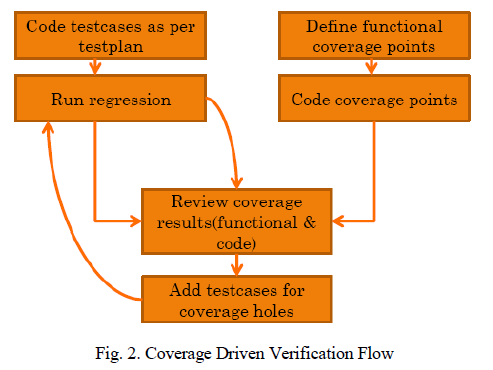
| How do we ensure all features are covered and Design is verified as per the specification? Close monitoring of functional coverage from initial stage allows verification team to align & focus efforts in right direction for verification sign off. Dedicated time and efforts need to be considered to make sure functional coverage is in aligned with the latest feature list. This approach adds one more check on correctness of feature verification along with maintaining traceability matrix. Ignoring functional coverage expectation updates can lead to functional coverage holes. Doing cross check with traceability matrix would save time for coverage closure activity. To avoid manual efforts of tracking and measurement and doing re-work on specification changes, a high degree of automation is again needed to extract all features from specification and map it to the verification & coverage plan in verification environment. |
 |
| The code coverage monitoring and analysis becomes very helpful for the evolving IP verification. It allows design team to see redundant code at the same time it would allow verification team to see any verification holes are there or not. The code coverage report when analysed by both design team and verification team at the same time would lead to use cases which may or may not be getting generated with randomization of the stimulus. |
CONCLUSION |
| It is well known fact that verification takes more than 70% of the time and effort in rolling out new Design IPs. If not planned well then verification team can lose valuable time in less important activities during the execution. We have tried to show simple steps which in reality saved lot of time and efforts. Also, a significant amount of time spent on Verification can be saved when executing new versions of standard. How you plan, process, manage and execute verification with proper architecture, flexible test benches, sanity check tests, tracking metrics with automation plays a vital role in delivering a quality product on time. |
ACKNOWLEDGMENT |
| I take this opportunity to express my deepest gratitude and appreciation to all those who have helped me directly or indirectly towards the successful completion of this paper. |
References |
|