Research & Reviews: Research Journal of Biology
ISSN: 2322-0066
ISSN: 2322-0066
Gangyan L1*, Qipeng S1,2 and Aoran Deng1
1School of Mechanical & Electronic Engineering, Wuhan University of Technology, Wuhan, China
2Luoyang Institute of Science and Technology, Luoyang, China
Received date: 05/03/2018; Accepted date: 12/03/2018; Published date: 19/03/2018
Visit for more related articles at Research & Reviews: Research Journal of Biology
The revolute pair plays a very important role in the precise and steady operation of planar heavy-load mechanism. This paper makes a comprehensive consideration of the influence of structure error, position error and the clearance in revolute pairs on the pose error. Based on the basic principles of the differential method, a new equivalent calculating method of the clearance is proposed in which the clearance is equivalent to the structure error and position error of the component. The continuous contact model is employed to establish a mathematical model of the clearance. According to the kinematic characteristic of the revolute pairs, the equivalent calculation is carried out for the fixed revolute pair and the moving revolute pair respectively. Finally, by the collaborative simulation of MATLAB and ADAMS, the pose errors of the planar heavy-load mechanism are obtained. The results of the calculations and simulation indicate that the effects of clearance size and orientation of the revolute pairs on the pose of the planar heavy-load mechanism are remarkable
Planar heavy-load mechanism; Pose error; Clearance; Differential method
The study on pose errors analysis is very important for the precise and steady operation of planar heavy-load mechanism. In classical analysis of mechanical systems all kinematic pairs are considered to be ideal or perfect, in which clearance, wear, and local deformation are neglected. However, in real systems there is always a gap associated with each pair. For instance, in a revolute pair a radial clearance is always present, which is an inevitable matter for the machining tolerances, wear, and imperfections. On the other hand, such clearance is necessary to allow relative motion between the components and makes them assemblage. But such clearance increases the wear rate, vibration and noise, especially in heavy-load mechanism.
The clearances exist in pairs have a great effect on mechanism’s pose. There have been many researchers[1-3] devoted to the investigation of clearance joints since 1980s. Weiliang et al. set up a matrix of propagation of error based on the differential method and proposed a position error calculating method. But the influence of clearance is ignored. Erkaya S regards the clearance as a mass-less rod and establish differential mathematical models to research the clearance’s influence on the pose error[4]. Many investigations have been devoted to the study of clearance. One approach used the statistical method, which treats the clearance as the dimensional tolerance[5]. Rao, considers the influence of the assembly clearance, dimension error and the maintenance factor on pose error from the kinematic point of view[6]. Kim J assumes that all random variables follow Gaussian distributions and analyze the influence of the clearance and dimension error[7]. Tsai introduces a generalized method for error analysis of multiloop mechanisms with joint clearance. Joint clearance is treated as a virtual link to simplify the study [8,9]. In order to improve the computing accuracy, Zhongchao and Lee, proposed the "equivalent length theory" to calculate pose error. But because the equivalent is less comprehensive, this theory could be improved [10,11].
In most pose error analyses, the size of the clearance is determined by the dimension of parts and the clearance angle is random. For convenience of calculations, the clearance angle is supposed to follow the normal distribution or uniform distribution. However, this approach is not fitting practical engineering. For a certain pose during the movements, the clearance angle is unique or changes within a small range. When some mechanisms have more than one revolute pairs, the above assumption has no regard for the interaction effect of clearance and will make the calculation error become large. For some planar heavy-load mechanisms, such as landing gear, jack mechanism, lifting mechanism and so on, the revolute pair is complicated and withstands the big radial direction load. In most of previous works, researchers considered only one clearance pair in the mechanical system, because considering more than one clearance-pair makes the analysis more complex. In this investigation, a new methodology is proposed to study the pose error of mechanical systems with multiclearance pairs. After an introduction, the paper is organized into four main sections. Section 2 introduces the revolute pair used in the planar heavy-load mechanism and differential method in pose error analysis while Section 3 describes the equivalent Calculating Method of Clearances using the massless link approach. In Section 4, a planar heavy-load mechanism with clearance pairs is studied and simulated as an example to demonstrate the efficiency of the proposed method. While a detailed discussion of the obtained results is presented. Finally, conclusions are outlined in Section 5.
Revolute Pair of The Planar Heavy-Load Mechanism and Differential Method In The Pose Analysis
The planar heavy-load mechanism is widely used in industrial manufacture and communication and transportation. Under the certain working condition, the structure and movement have distinctive characteristics. Because of the heavy load, the revolute pair composed of axles and holes cannot meet the strength requirements, it is necessary to add some bearing parts. Compared with some simple revolute pairs, the accumulated clearances of revolute pairs of the planar heavy-load mechanism are more complex and will make great influence on the pose. The direction of revolute pair’s clearance is not random, but related to the stress state in different working position. According to the structure and movement characteristics of the planar heavy-load mechanism, the influence of the clearance should be studied in the pose error analysis.
Based on the differential method, we can replace differential dx with error Δx in the pose error analysis. By the constraint equations, the unknown pose error related with the input error, the structural error and the position error can be calculated.
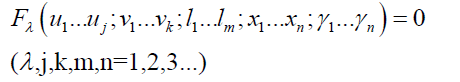
The constraint equations of the planar heavy-load mechanism are defined as follows
 [1]
[1]
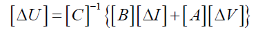
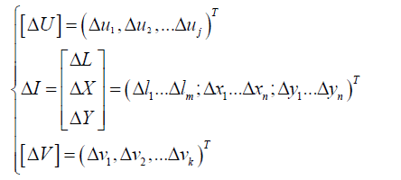
Where uj, vk, lm, and (xn,yn) respectively represent output parameters, input parameters, structural parameters and position parameters. By the derivative of the λ sets of equations and matrix transformation, the relation equation about these parameters can be shown [1]:
 [2]
[2]
 [3]
[3]
Where A, B and C respectively represent the coefficient matrix which are calculated by the derivative of related variables.
Through the differential method, the error model can reflect the influence of different error parameters on the output parameters. But when taking clearance into account, each clearance will introduce two variables (the size of the clearance r and the clearance angle θ). The constraint equations become more complicated, and the solutions are not unique. So the differential method does not apply to the pose error calculation about clearances.
Equivalent Calculating Method of Clearances In Revolute Pairs of The Planar Heavy- Load Mechanism
Basic Assumptions of the Equivalent Calculating Method
In order to introduce the clearance vector directly, this section assumes the following assumptions.
The clearance of revolute pairs accords with the continuous contact model. Assume that these elements of revolute pairs are in a state of continuous contact and won’t fall apart. The continuous contactmodel is shown in Figure 1. The offset of axis of axles and holes can represent the revolute pair’s accumulated clearance and it can be equivalent to a mass-less rod.

Figure 1: Continuous contact model of the clearance.
In Figure 1 the distance between O’ and O represents the accumulated clearance r. It is related to the components’ fit dimensions. The clearance angle θ represents the angle between the x-axis and the mass-less rod. For some low-speed and heavy-load mechanism, external force and the low speed operating state will make components contact with each other closely. The continuous contact model applies to this case.
Clearance is one kind of structure parameter. But in that clearance between vital parts is very small compared with the dimension of the parts, it can be regarded as an error.
If the bearing condition of the mechanism is determinate in a certain pose, the clearance angle θ is also determinate. But since that it is hard to make certain direction of each part’s force if we take the clearance into account. And the clearance angle is also hard to solve accurately. However, clearance is very small compared with the dimension of the parts and the influence on mechanism’s force can be neglected. On this occasion, the clearance angle approximately equal to the parts’ forced direction in the instance that the clearance is not considered.
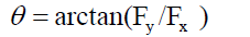
The clearance angle is defined as follows:
 [4]
[4]
Where Fx and Fy are the stress state of a revolute pair.
Based on the above assumption, the size of the clearance of each revolute pair at a certain pose can be determined. Clearance is regarded as an error. However, Equation (2) still cannot apply to mechanism’s pose error calculation because these variables do not include clearance. So it is necessary to make clearance be equivalent to the known variables in Equation (2).
Equivalent Calculating Method of Clearances of Revolute Pairs:
For a fixed revolute pair, the clearance can be equivalent to this revolute pair’s position error.
As shown in Figure 2, the ordinate origin O is the ideal position of the axis of revolute pairs. When regardless of the clearance error, the point O is also the end of the motion rod. When the revolute pair exist the position error (Δx’, Δy’), the end of the motion rod transfers from O to O1. And when taking the clearance in to account, the end of the motion rod transfers from O1 to O2. Assume the actual coordinate of the end of the motion rod is (Δx, Δy).

Figure 2: Error schematic diagram of a fixed revolute pair
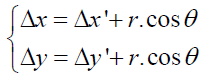 [5]
[5]
For a moving revolute pair, the clearance can be equivalent to the structural error or input error of the rod related to the revolute pair.
A moving revolute pair composed of two rods is shown in Figure 3, and the two rods respectively have the structural error Δl1’ and Δl2’. Making the clearance project in two rods’ direction, and the equivalent errors of rods can be calculated from the following expressions:

Figure 3: Error schematic diagram of a moving revolute pair.
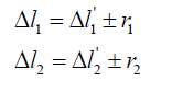 [6]
[6]
Where r1 and r2 respectively represent the projections of the clearance in the two rods. And the plus-minus sign depends on the situation whether the projections of the clearance make the rods longer or shorter. As is shown in Figure 3, Assume that the angle between rod 1 and x-axis is α1, and the anticlockwise angle between rod 1 and rod 2 is α2 (0~ π ). At the movement of the mechanism, these angles are changing. For the sake of the convenient calculation, use the x-axis as the benchmark of the clearance angle θ. And the new clearance angle is γ (γ=θ-α1). Because of its symmetry of structure, the projection calculating of the clearance has the following characteristics
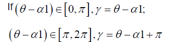
And the equivalent errors is represented as:
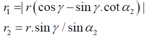 [7]
[7]
By such an equivalent method, the differential of the constraint function is linearly varying in the local context and making it possible to use differential method to solve the computational problem of pose errors.
Application of the equivalent calculating method
Calculation Example of the Pose Error of the Planar Heavy-load Mechanism.
A vehicle radar lifting mechanism is shown in Figure 4. As the reference for installation of the antenna array and support component, the platform’s pose will directly affects radar working precision. And components’ structural errors, position errors and clearances will cause the pose errors of platform. The mechanism is studied as shown in Figure 4.

Figure 4: Parametric diagram of the vehicle radar lifting mechanism.
The motion constraint equation of the mechanism is shown in Equation(8):
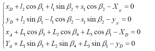 [8]
[8]
Where β1 is the motion angle which represents the motion position of the platform in the process of lifting. β4 is the pose angle which represents the incline of the platform. Taking a derivative with respect to input parameter s, the matrix A is obtained as shown in Equation (9).
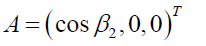 [9]
[9]
Taking a derivative with respect to structure parameters l1, l2, L1, L2, L3 and positional parameters xA, yA, xD, yD, xN, yN, the matrix B is obtained as shown in Equation (10).
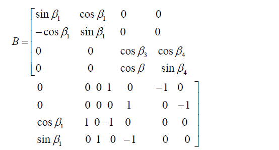 [10]
[10]
Taking a derivative with respect to output parametersβ1, β2, β3 and β4, the matrix C is obtained as shown in Equation (11).
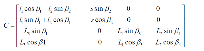 [11]
[11]
The equivalent errors can be obtained from Equation (4), (5), (6) and (7) as shown Eq. (12) and (13).
 [12]
[12]
 [13]
[13]
From the above, the error model is shown in Equation (14).
 [14]
[14]
Collaborative Simulation of ADAMS and MATLAB
In the process of lifting, the stress state of revolute pairs will change invariably. In order to make the calculation more convenient, the stress state of revolute pairs can be analyzed by the dynamic software ADAMS. The dynamic model of the lifting mechanism is shown in Figure 5.

Figure 5: Dynamic model of the lifting mechanism.
Importing the simulation data into MATLAB and the stress diagram of curves of revolute pairs can be obtained as shown in Figure 6.

Figure 6: Stress diagram of curves of the revolute pair A, B and C.
According to Equation (4) and the data in Figure 8, the clearance angles can be calculated by MATLAB. Substitute these clearance angles into Equation (5), (6) and (7) and the equivalent errors of clearances can be obtained as shown in Equation (15).
 [15]
[15]
According to the equivalent errors, the pose errors in different positions can be obtained by Equation (14). Above all, β1 and 4 are the important indicators which evaluate the pose of the lifting mechanism and should be given due attention. Δβ1 and Δβ4 are shown in Figure 7.

Figure 7: Stress diagram of curves of the revolute pair D, M and N.
As can be seen from Figure 8, Δβ1 and Δβ4 are different in different positions. With an increase in the screw’s travel, Δβ1 will gradually increase and Δβ4 will drop off.

Figure 8: The error schematic diagram of Δβ1 and Δβ4
The clearance angle of the revolute pair will change in different positions because of the different stress state. Due to the directivity of the clearance, some equivalent errors will enlarge the pose errors and some equivalent errors will reduce the pose errors. Especially the lifting mechanism has several revolute pairs and the pose errors will be affected by their comprehensive influence. When the clearance’s direction of some revolute pair changes greatly, the calculated error curve will sharp fluctuate.
Take the lifting mechanism for example, as is shown in Figure 7, the forced direction of revolute pair C changes from the third quadrant to the second quadrant when the screw’s travel is around 200 and the influence of the equivalent error on Δβ1 decrease first then increase. So the error curve’s increase speed in Figure 7 changes a lot compared with the situation in which clearances are not considered. And the influence on Δβ4 is just the opposite. The characteristic of the clearance’s directivity has a great influence on pose errors, especially for some mechanisms containing multiple revolute pairs where the influence is very prominent. And the characteristic should be taken into account.
This paper presents a computing method for studying influence of clearance-affected pairs on the pose error. Based on the traditional differential method, a new equivalent calculating method of clearances has been proposed. With respect to other methods in the literature, this new method is more accurate and complete, because the consideration of clearance is closer to practice. By the collaborative simulation of MATLAB and ADAMS, the pose error of a vehicle radar lifting mechanism is obtained.
This method simplifies the calculation process. Compared with the error analysis method in which the clearance is ignored or the clearance angle is supposed to follow the normal distribution or uniform distribution, the result in this paper can reflect a better picture of the clearance’s influence on pose error, with special emphasis on directional characteristic of the clearance.