Research & Reviews: Journal of Pure and Applied Physics
ISSN: 2320-2459
ISSN: 2320-2459
Pawan Kumar Kuldeep, Sanjay Kumar, Subhash Chandra, Mahendra Gora, Arivnd Kumar, Sunita Mahavar*
Department of Physics, University of Rajasthan, Jaipur, India
Received : 06-Oct-2022Manuscript No. JPAP-22-76641; Editor assigned: 10-Oct-2022 Pre QC No. JPAP-22-76641(PQ); Reviewed: 24-Oct-2022, QC No. JPAP-22-76641; Revised: 31-Oct-2022, Manuscript No. JPAP-22-76641(A) Published: 07-Nov-2022, DOI: 10.4172/2320-2459.10.5.006
Visit for more related articles at Research & Reviews: Journal of Pure and Applied Physics
A solar receiver system collects solar radiations in a solar concentrator system and transfers the heat to the working fluid of the system for useful thermal application. In the present work two locally fabricated receiver designs are experimentally investigated on a solar parabolic dish concentrator having an aperture area of 7 m2 and a rim angle of 56°C. Based on sensible heat test of fluid, two thermal performance parameters, rate of rise of fluid temperature, Rf, and utilizable efficiency of system, ηu, are determined and are recommended for the comparative study of different receivers. The experiments are conducted with two fluid, water, flow rates 8 L/min and 10 L/min for the receivers, flat copper spiral receiver, CSR, and copper conical spiral receiver, CoSR. The Rf for CoSR and CSR receivers are found to be 0.33 and 0.23°C/min, respectively for 8 L/min flow rate. The utilizable efficiency of CoSR and CSR are determined to be 33% and 17%, respectively. The receiver surface temperature of CSR is found higher than CoSR due to less efficiency of CSR. It is found in the experimental observation that the sensible heat test procedure clearly differentiates the performances of receivers and is appropriate to study the thermal performance of different receiver designs.
Nomenclature
Aa Aperture area of the concentrator (m2)
Ar Receiver base area (m2)
CR Concentration ratio; Cw Specific heat of water (J/kg°C)
Da Concentrator diameter (m)
Ib Normal beam solar irradiance on concentrator aperture plane (W/m2)
Is Global solar irradiance on horizontal plane (W/m2)
Is, avg Average global solar insolation at the horizontal surface (W/m2) in time period Δt
Mw Mass of water in the storage tank (kg)
qa Available rate of heat to the fluid (W)
qu Utilized rate of heat by the fluid (W)
S Solar flux absorbed in receiver plate (W/m2)
Ta Ambient temperature (°C)
Tr Receiver stagnation temperature (°C)
Tw Water temperature in storage tank (°C)
Tw,f Water temperature in storage tank at the end of heating process (°C)
Tw,I Water temperature in storage tank at the beginning of heating process (°C)
Ws Wind speed (m/s)
Greek symbols
αr Absorptivity of receiver paint
Δt Time interval (s)
ηu Utilized thermal efficiency of concentrator
ρr Specular reflectance of the reflector
θ Average angle of incidence on the horizontal surface (°)
Acronyms
ESPC Economic Solar Paraboloidal Concentrator
SPDC Solar Paraboloidal Dish Concentrator
HTF Heat Transfer Fluid
CSR Copper Spiral Receiver
CoSR Copper Conical Spiral Receiver
CFP Circular Flat Plat
Solar receiver; Heat transfer fluid; Thermal heat storage; Dish concentrator
Among various renewable energy resources, solar energy is one of the potential sources of energy to meet thermal as well as electric energy demand of the world. Presently, on the one hand solar Photovoltaic (PV) technology is contributing into the electricity demand through conversion of thermal energy into electricity, while on the other hand solar flat plate and concentrator technologies are fulfilling the thermal energy demand through photo-thermal conversion. The solar concentrating technology has multiple applications. The powerful solar concentrator’s viz parabolic dish concentrator and linear Fresnel reflectors are used for power generation while other concentrating technologies like compound parabolic concentrator and parabolic trough concentrator are used for low to medium temperature heating applications. A Solar Parabolic Dish Concentrator (SPDC) concentrates the received solar radiations on a point focus area. A receiver mounted on that focus area absorbs the radiation and utilizes the collected heat through a circulating Heat Transfer Fluid (HTF) that is flowing into it. The collected heat through the HTF is further stored in a heat storage tank. For the proper functioning, the system requires a precise dual axis tracking of the sun through a solar tracker. There are different design parameters, components and the properties of components which affect the optical and thermal performance of a SPDC. The design of a receiver plays an important role in the capturing and collecting the solar energy, and hence significantly affects the thermal performance of a concentrator system. The receiver design should be such that it can collect the concentrated solar radiation and transfer it into HTF with minimal heat losses. A number of theoretical and experimental researches have been conducted for receiver selection and design to achieve high thermal performance of a concentrator. A detailed review of different types of cavity receivers, cylindrical, hemispherical, conical, and flat, had been presented by Kasaeian, et al. [1]. A comparison of optical and thermal performance parameters were incorporated in the paper. It was found that a hemispherical cavity receiver, with a spiral-coil upon the external surface and a reflector around the cavity aperture side, had the highest thermal efficiency. Loni, et al. had presented a detail review on various studies conducted for experimental and numerical analysis of the solar dish cavity receivers [2]. In this paper different cavity receivers are also studied experimentally using different nanofluids such as Al2O3/oil, MWCNT/oil, and SiO2/oil. The recommendations are made in the favor of hemispherical which is found most efficient among all. Thirunavukkarasu, et al. performed the fabrication and testing of a flat spiral tube receiver on a Scheffler dish concentrator [3]. Water was used as heat transfer fluid in the experiments with a flow rate of 1.5 L/min connected to a storage tank of 85 L capacity. An experimental investigation of flat surface absorption receiver with metal fins was made by Senthil, et al. on a Scheffler dish concentrator diameter of 2.5 m [4]. A maximum surface temperature of 468°C was reported. It was observed that incorporation of fins in the designed significantly improved the thermal performance of the receiver. Pavlovic, et al. investigated a spiral shape absorber on low-cost solar dish collector of diameter 3.8 m [5]. They also developed a numerical model to examine the performance of receiver with different HTFs. The highest efficiency was observed for thermal oil with inlet temperature of 155°C. A comparative study of spiral receiver and conical receiver inside a cavity was performed by Sasa, et al. through a solar dish concentrator of aperture area 10.29 m2 [6]. For high temperature HTF, the thermal efficiency of conical receiver with cavity was found significantly higher about 40% than the spiral receiver. In the optical performance the spiral receiver temperature (394°C) was observed to be 200K higher than the conical receiver (187°C) that is also a reason of poor thermal performance of spiral receiver. Two types of receivers, cylindrical and conical tube, were experimentally investigated by Hassan, et al. on a paraboloid dish concentrator [7]. It is over served that conical tube receiver had better optical efficiency and stagnation temperature than the cylindrical cavity. Water was used as working fluid and a flow rate of 0.83 L/minute is maintained in the experiments. An investigation on cylindrical cavity receiver with insulation was conducted by Azzouzi, et al. [8]. The experimental and analytical study was performed using a solar paraboloidal concentrator having aperture area of 1.67 m2. Different positions were studied and a variation in thermal efficiency with different water flow rate was estimated. An efficiency of 56% at 8 L/min flow rate was quoted for the receiver. Sinha, et al. carried out a heat loss study of a three coil cavity receiver made of copper tube using an indoor lab set-up [9]. The performance of the receiver is found better than a single coil cavity receiver. Mawire, et al. investigated the thermal performance of cylindrical cavity receiver using a SK-14 parabolic dish concentrator [10]. The optical efficiency of the system was determined to be 52%. An experimental study of a cylindrical cavity receiver was performed by Loni, et al. using carbon nanotube/oil nanofluids as heat transfer fluid [11]. It was observed that the thermal efficiency of the cavity receiver improved by 13.12%, due to use of MWCNT/thermal oil nanofluid. Loni, et al. also investigated a hemispherical cavity receiver using MWCNT/oil nanofluid [12]. The thermal efficiency of this receiver was found to be 76% with MWCNT/oil nanofluid. Wang, et al. had proposed an innovative taper annulus structure for the solar dish cavity receiver based on computer simulation using Tracepro software to simulate the ray tracing [13]. It was found that new design had considerably uniform power profile on both of the cavity and the absorber wall which increased its thermal performance. For high temperature application an air cavity receiver with Reticulated Porous Ceramic (RPC) was experimentally studied by Patil, et al. [14]. Three RPC materials, silicon- infused silicon carbide or SiSiC, alumina, and ceria, were tested. The highest efficiency of 69% was achieved by the SiSiC at an air outlet temperature of 1133°C. The performance of receivers is also investigated through simulation in a few references. Kalidasa, et al. had done a simulation study on different shapes of receivers, flat, spherical, dome, cylindrical and frustum of cone shape, using solid works 16 and fluid simulation [15]. Different configuration of receivers was analyzed for a dish concentrator and it was found that spherical cavity receiver was the most efficient receiver among all. Using solid works Flow Simulation, Bellos, et al. had investigated deferent types of cavity receivers which were cylindrical, rectangular, spherical, conical and cylindrical-conical [16]. The efficiency of cylindrical conical shape was found 67.95% which is maximum among the all. Daabo, et al. used an advanced ray tracing method to simulate the optical efficiency of different geometries, cylindrical, conical and spherical, of cavity receivers [17]. The optical efficiency was found to be maximum about 75.3% for the conical shape receiver. A simulation study to evaluate the optical and thermal performance of a cylindrical cavity receiver was performed by Xiao, et al. [18]. The performance was investigated through a solar dish concentrator of diameter 2.88 m and effects of various positions of receiver on the dish performance were examined in this study.
The above review infers that receivers’ designs are of mainly two types, flat and cavity. In the flat geometry spiral tube receivers are tested while in the cavity type, different types of cavities, conical, cylindrical, hemispherical etc. are studied [19]. The review also infers that the performance of receiver can be analyzed through stagnation temperature, thermal efficiency and heat losses [20]. All these parameters also depend on receiver coating, receiver orientation, type of heat transfer fluid, flow rate of HTF, properties of dish reflector, concentrator ratio, solar insolation, wind speed and ambient temperature. Different receiver designs and their performance parameters are summarized in Table 1. In this table only those research work are included in which water is used as HTF and receiver material is of copper. Mostly receivers are studied using a solar paraboloidal concentrator. The table indicates a large variation 34% to 74% in thermal efficiency; this is due to the other affecting parameters during testing mentioned above. Therefore, in order to study any receiver design a comparison with reference work would not provide adequate results. So, the receivers should be tested on an equal set-up under equivalent weather conditions. Moreover, a close study of reference work has inferred that the stagnation temperature of flat receiver determines the optical efficiency of the system, yet for other receiver shapes this procedure would not give relevant results. A sensible heat test of fluid in a close loop circulation is found suitable for the study of different receivers under identical system and weather parameters. The paper presents the investigation of the thermal performance of a solar paraboloidal dish concentrator using two types of receivers. The dish, Economical Solar Paraboloidal Concentrator (ESPC), is designed and fabricated at Solar Energy Research Laboratory (SERL). The receivers, spiral and conical shapes are fabricated locally. In the thermal performance test only sensible heat test using water as heat transfer fluid in a close loop is conducted and performance parameters viz rate of rise of fluid temperature (heating rate) and utilized thermal efficiency are computed. The simple test procedure which is described in the paper for the comparative study of different receivers can be flowed for study of different receiver designs.
| Reference | Concentrator aperture area (m2) | Receiver | Receiver stagnation temperature (°C) | Maximum water temperature (°C) | Thermal Efficiency | Average solar insolation |
|---|---|---|---|---|---|---|
| Shape and area (m2) | (%) | (W/m2) | ||||
| Thirunavuk-karasu, et al. [3] | 16 | Flat spiral tube, 0.125 | 366 | 91 | 56 | 750 |
| Pavlovic, et al. [5] | 11.33 | Flat spiral | - | 56 | 34 | 900 |
| Hassan, et al. [7] | - | Cylindrical cavity, 0.20 | 300 | - | 59 | 840 |
| Hassan, et al. [7] | - | Conical cavity, 0.20 | 330 | - | 62 | 840 |
| Subramani, et al. [19] | 1.76 | Conical cavity | - | 70 | 77 | 878 |
| Reddy, et al. [20] | 20 | Modified hemispherical cavity receiver | 400 | - | 74 | 641 |
Table 1. Details of receivers and their performance parameters in reference papers.
Solar thermal concentrator system
A solar thermal concentrator system mainly has following main components for the proper function: (i) a concentrator with tracking system (ii) receiver or absorber and (iii) a storage system. In the present work a concentrator system is a point focus paraboloidal dish which is locally designed under a DST funded project. The dish is named as Economical Solar Paraboloidal Concentrator (ESPC). Two receiver designs are fabricated to test the thermal performance of the dish and a storage system is attached to the whole system for the proper collection of the heat through a circulating HTF in a close loop.
Economical solar paraboloidal concentrator
The paraboloidal dish, ESPC, of 3 m diameter is fabricated at solar energy research laboratory. The rim angle and focus distance of the dish are 56°C and 1.40 m, respectively. The paraboloidal shape of dish is consisting of 4 wings as shown in Figure 1a. Each wing has 6 trapezoidal flexible stainless-steel reflector sheets. The dimension details of a single wing are depicted in Figure 1b. These four wings are adjoining through a circular dish of 0.45 m diameter while keeping an estimated gap of desired distance. Complete paraboloidal structure is also supported through L shape rings behind the structure. To hold a receiver a metallic ring is adjusted at little higher distance than the focal point through the support of four iron roads. One end of iron road is connected to the metallic ring and other end is bolted between the gaps of 4 wings. A dual axis tracking system includes two electronic linear actuators whose motions are controlled through a real time clocked based electronic control unit.

Figure 1a: Paraboloidal dish system with receiver and storage system.

Figure 1b: Dimension detail of a wing of paraboloidal structure.
Receiver system
Two receiver designs are experimentally investigated in the present work. Both are fabricated using a copper tube of 0.0127 m outer diameter. Through the precision molding of the copper tube a Copper Spiral Receiver (CSR) and a Copper Conical Spiral Receiver (CoSR) are designed. The outer (D1) and inner (D2) diameters of CSR are 0.228 m and 0.102 m, respectively. Total numbers of rings are 5 and total length of copper tube is 2.70 m. In CoSR, the bottom (D1) and upper (D2) circular ring diameters are 0.145 m and 0.095 m, respectively. The numbers of copper tube rings are 13 and total length is 4.9 m. The height (H) of frustum cone is 0.15 m. Both these receivers are supported through a Copper Flat Plate (CFP) of 0.30 m diameter (Y) and 0.001 m thickness. The schematic of both receivers are depicted in Figures 2a and 2b. The Copper Flat Plate (CFP) has 4 holes, two holes are used to attach the plate with the receiver ring and two holes support the CSR or CoSR. Two bolts of length 0.30 m connect the plate to the receiver ring. The adjustable lengths of bolts provide the desired mounting distance to any receiver. The weight of CSR and CoSR including CFP are about 1.2 kg and 1.4 kg, respectively. The concentration ratio of CSR and CoSR are 173 and 428, respectively. To increase the heat collection in CoSR a few aluminum fins are inserted in the gap between CoSR and CFP. A black matt paint is used for coating of the receivers. Both the receivers are shown in Figures 3a and 3b. A common heat transfer fluid, water, is selected for the testing of receiver’s thermal performance.

Figure 2a: Schematic of CSR, D1=0.228 m and D2=0.102, Y=0.30 m.

Figure 2b: Schematic of CoSR, D1=0.145 m and D2=0.095, Y=0.30 m, H=0.15 m.

Figure 3a: Copper spiral receiver attached to copper flat plate.

Figure 3b: Copper conical spiral receiver attached to copper flat plate.
Heat storage system
For the heat collection a Poly Vinyl Chloride (PVC) storage tank is connected in a close loop to the receiver system. The heat storage system has 3 holes as shown in Figure 4. The hole at point 1 is used to dip two sensors at desired location. The water inlet to the storage tank is at point 2 and point 3 is for water outlet. The PVC tank has dimension of 0.50 × 0.50 × 0.246 m3 and has water capacity of 60 L. The system is thermally insulated through a multilayer hybrid insulation of glass wool and cardboard of thicknesses 0.050 m and 0.010 m, respectively. A 12 V DC pump of flow rate of 10 L/min is used to circulate the water from receiver system to collect the heat and to store the heat in the tank. To control the flow rate a mechanical water flow valve is connected to adjust it manually for different flow rate conditions. The heat line between receiver and storage tank is made of flexible silicone pipe of 0.02 m diameter that is thermally insulated by mineral wool of thickness 0.01 m. The pipe length is kept sufficiently large as azimuthal rotation of the dish covers a large distance.

Figure 4: Schematic of the HST. Note: 1: Sensors inlet; 2: HTF inlet; 3: HTF outlet; a=0.50 m, b=0.50 m, c=0.246 m.
Thermal performance test parameters
Three thermal performance parameters can be estimated for a solar concentrator system (i) receiver’s stagnation temperature, Tr, (ii) rate of rise of fluid temperature i.e. heating rate, Rf, and (iii) utilizable efficiency of thermal storage system, ηu. For the stagnation temperature measurement, the receiver is exposed to the solar radiation without any flow of HTF. The highest attained temperature by the receiver is the stagnation temperature. But it is observed during the testing that although, high receiver stagnation temperature is a direct indication of high optical performance of the concentrator, yet it is applicable for flat receivers only. For different shapes of receiver stagnation temperature test cannot be recommended as flux distribution pattern differs than the flat receivers which cause low stagnation temperature. The same observations are also made. Therefore, in the present study stagnation temperature test is not performed. The receiver shape directly influences the heat collection and the storage tank temperature. Hence, a sensible heat test, in which a HTF is flowed through the receiver and is stored in a storage tank, can be recommended to test the different designs of the receivers. In the sensible heat test, the temperature of fluid initially increases rapidly that is transient state and after reaching its maximum value a steady state is achieved. The rate of rise of fluid temperature or heat transfer to the fluid i.e. Rf, in the transient state and the utilizable efficiency of storage tank in the steady state are the performance parameters to evaluate the thermal performance of the concentrator as well to perform a comparative study of different receivers in the identical weather conditions. The rate of rise of fluid temperature, Rf, is simply the slope of linear curve between the fluid temperature and time in the transient state. The utilizable efficiency, ηu, of the storage tank can be determined through the following expression:
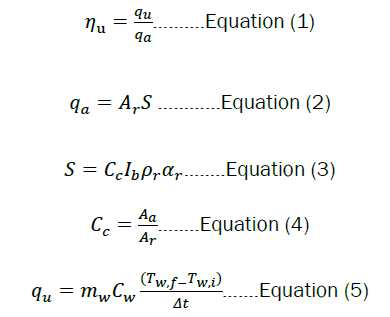
In the above relations, the utilizable rate of heat and available rate of heat are denoted by qu and qa, respectively. The absorbed solar insolation, S (W/m2), depends on concentration ratio, Cc, normal beam irradiation at the paraboloidal surface, Ib, reflectance of reflector ρr and absorptivity of the receiver paint αr. The concentration ratio is the ratio of the aperture area of the dish to the base area (Ar) of the receiver. If, solar insolation is measured on a horizontal surface than 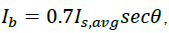 is a good approximation for the location at Jaipur, where Is, avg is the average global solar insolation at the horizontal surface (W/m2) during the time period Δt. The average angle of incidence on the horizontal surface is denoted by θ. The mass and specific heat of the fluid are mf and Cf, respectively. The initial and final average temperatures of the water in the storage tank are denoted by Tw,i and Tw,f, respectively. The time interval to reach till final temperature is Δt in minute. In the expression of utilizable efficiency, the utilizable rate of heat through the receiver and storage tank material is not considered to observe the direct effect on fluid temperature due to receiver design.
Experimental investigation
For the experimental investigation of the receivers, the sensible heat tests are conducted on sunny days in May 2022. The storage tank of capacity 60 L is filled with 50 L of distills water and water is circulated using the DC pump into the mounted receiver. Two flow rates, 8 L/min and 10 L/min are kept in the experiments with both the receivers. The flow rate is manually controlled through a flow valve. The schematic of test set-up is shown in Figure 5 and on-field set-up can be seen in Figure 1. All the experiments are performed at the roof top of Solar Energy Research Laboratory (SERL), University of Rajasthan, Jaipur (26.92°N, 75.87°E), and India. The storage and receiver temperatures and, weather parameters (ambient temperature, solar insolation and wind speed) are measured in every 05 minute interval for the duration of 10:30 to 14:00 IST. In all these experiments, the solar radiation intensity (Is, W/m2) and wind speed (m/s) are measured using automatic weather station (hydromet, accuracy ± 5 W/m2, ± 0.1 m/s). Two-point contact thermocouples (range -50°C to 200°C) are dipped at different heights in the storage tank and using CIE-305 thermometer (accuracy ± 0.1°C) the Water Temperatures (Tw) are measured in every 5 minute time interval. The ambient temperature is measured using a mercury thermometer (accuracy ± 0.1°C) placed in an ambient chamber. For the measurement of surface temperatures (Tr) of the receivers, a K-type thermocouple (range -10°C to 600°C) is attached near the CFP in both the receivers. The K-type sensor temperature is recorded through a data logger (Masibus 85XX+) which is connected through a computer that uses mSCAN+software to record the data. The thermography images of the receivers are also taken using a thermal imaging camera (Fluke Ti32s) having accuracy ± 0.01°C.

Figure 5: The schematic of the outdoor experimental setup.
The thermal profiles of CSR and CoSR receivers in a closed loop water circulation are depicted in Figures 6 and 7 for 8 L/min flow rate and 10 L/min, respectively. The variation of storage water tank temperature, ambient temperature and solar insolation with Indian Standard Time (IST) are plotted in the figures. The surface temperatures of the receivers along with wind speed data are plotted in Figure 8. The transient temperature profiles of water with both the receivers and flow rates are plotted in Figures 9, 10a, 10b, 11a, and 11b show the thermography images of both the receivers. The temperature distribution of both receivers is also shown in 3D view using Fluke smart View R & D thermal imaging software in Figures 12a and 12b.

Figure 6: Variation of solar insolation, storage water temperature and ambient temperature with Indian Standard Time (IST) for CSR and CoSR with 8 L/min water flow rate on 2 May, 2022 and 09 May, 2022, respectively. 

Figure 7: Variation of solar insolation, storage water temperature and ambient temperature with Indian Standard Time (IST) for CSR and CoSR with 10 L/min water flow rate on 3 May, 2022 and 10 May, 2022, respectively.

Figure 8: Transient temperature profile of heat storage tank with Copper Spiral Receiver (CSR) and Copper Conical Spiral Receiver (CoSR) for flow rates 8 L/min and 10 L/min.


Figure 9: Variation of receiver temperature (Tr) and wind speed (Ws) with Indian Standard Time (IST) for CSR and CoSR with on 2 May, 2022 and 9 May, 2022, respectively.


Figure 10a: Thermography image of CSR with water flow rate 8 L/min.

Figure 10b: Thermography image of CoSR with water flow rate 8 L/min.

Figure 11a: Thermography image of CSR with water flow rate 10 L/min.

Figure 11b: Thermography image of CSR with water flow rate 10 L/min.

Figure 12a: Temperature distribution of CSR in 3D view.

Figure 12b: Temperature distribution of CoSR in 3D view.
Figures 6 and 7 depict that storage water temperature increases linearly in the transient state of initial one hour and after 13:00 IST reaches to the maximum. The average solar insolation, Is, on the experimental days with 8 L/min flow rate remained nearly 742 and 747 W/m2 for CoSR and CSR, respectively. This provided a condition of almost equal solar insolation condition for the comparative study of the receivers. Under this condition the maximum temperature of storage water tank reached temperature of 70°C with CSR and 80°C with CoSR. A 10°C temperature increment was observed with CoSR. With flow rate of 10 L/m in Figure 7, the average solar insolation on 3 May recorded about 754 W/m2 and 727 W/m2 on 10 May. It reflects slightly better insolation on CSR test day. The maximum water temperatures with CSR and CoSR were found to be 67°C and 79°C, respectively. The average ambient temperatures during all experiments were recorded to be between 37°C and 38°C. The rate of rise of storage tank temperature, Rf, is computed using the curves plotted in Figure 8 in the transient state. The Rf for CSR with flow rates 8 L/min and 10 L/min are found to be 0.23°C/min and 0.20°C/min, respectively and, for CoSR with flow rate 8 L/min and 10 L/min Rf are figured to be 0.33°C/min and 0.31°C/min, respectively. These observations from Figures 6-8, infer that the performance of CoSR is better than CSR. For both the receiver test results with 8 L/min flow rate are found comparatively better than 10 L/min flow as expected. Using Equations (1) to (5), the utilizable thermal efficiency of both the receivers are computed using the thermal profiles presented in Figures 6 and 7. In this computation, the diameter of CSR and CoSR are 0.228 m and 0.145 m, respectively. The concentration ratios are 173 and 428 for CSR and CoSR, respectively. The specific heat of water is taken 4186 J/kg°C. The reflectivity of stainless-steel sheet reflector is about 0.78 and absorptivity of matt black paint is considered to be 0.90. The average angle of incidence for CSR and CoSR are about 9° and 11°, for the experimental days in the month of May. Table 2 includes both transient state and steady state performance parameters along with other experimental data for both the receivers. The utilizable efficiency, ηu, with CSR and CoSR receivers are found to be 15% to 17% and 32% to 33%, respectively. Clearly, the conical shape receiver, CoSR, performance is better than a flat receiver, CSR. The efficiencies of these receivers are not compared to the reported reference in Table 1 as there are various factors which affect the efficiency viz concentration ratio, properties of reflector etc. So a fare comparison cannot be done. The efficiency of CoSR which is about 33% can be more improved through the use of high reflecting surface than the present one. There is also a need to minimize heat losses through receiver and heat pipe line. The receiver surface temperatures are reported in Figures 9-12. The profile in Figure 9 clears that on experimental day the wind velocity remained less that 2 m/s, which provided a good weather condition for this comparative study. The average receivers’ temperatures from Figure 9 are found to be 330°C and 236°C, for CSR and CoSR, respectively. The observation of thermography image infers that the temperature of CSR remained around 302°C to 328°C and about 116°C to 125°C in case of CoSR. Due to flat surface of CSR the temperature reported in Figures 9-11 are in well agreement but, the conical shape of CoSR causes a major difference in the temperatures reported in Figures 9-11. The 3D thermal image in Figure 12 illustrate temperature distribution varies with the height of the receiver. This variation is large in case of CoSR than CSR. The data presented in Figures 9-12, illustrate that the surface temperature of CSR remained higher than the CoSR due to flat shape; nevertheless it does not improve its performance during the sensible heat test. Clearly, the high receiver temperature is not an indicator of good performance under real application. A sensible heat test conducted in the close loop is a more appropriate test procedure for study. The rate of rise of fluid temperature and the utilizable efficiency are suitable thermal parameters to analysis the effect of different shapes of receivers.
| Receiver | Flow rate | Transient state | Steady state | ||||||
|---|---|---|---|---|---|---|---|---|---|
| (L/min) | Rf (°C/min) | S (W/m2) | Tw,i (°C) | Tw,f (°C) | qa (W) | qu(W) | Δt (min) |
ηu (%) | |
| CSR | 8 | 0.23 | 64740 | 36 | 70 | 2641 | 440 | 270 | 17 |
| 10 | 0.2 | 65346 | 36 | 66.7 | 2666 | 397 | 270 | 15 | |
| 8 | 0.33 | 158022 | 36 | 80.2 | 2608 | 858 | 180 | 33 | |
| CoSR | 10 | 0.31 | 154828 | 36 | 77.7 | 2555 | 810 | 180 | 32 |
Table 2. The thermal performance parameters of the receivers.
In a solar concentrator, the receiver shape is one of the influencing factors to the thermal performance of the system. Various designs have been tested and suggested so far for solar dish concentrators. Different test procedures and parameters are suggested in references for optical and thermal performance study. In the present paper the testing of two types of solar receivers are reported. These receivers, one is flat spiral (CSR) and the other is conical cavity (CoSR), are fabricated through the precise molding of a copper tube. The Experimental Study Is Performed on a Dish Concentrator (ESPC). The experimental investigation can be concluding in the following points:
(i) In the present work it is observed that optical performance which is determined through the stagnation test cannot be determined for different shapes of receiver through this test. So, for the comparative study of receivers this test should not be suggested.
(ii) The sensible heat test under the flow of heat transfer fluid in the close loop provides two decisive parameters: (a) rate of rise of fluid temperature Rf (b) utilizable efficiency of the system, ηu, to study the thermal performance of a concentrator and to determine efficiency of different receivers.
(iii) The thermal performance of CoSR is found better than the CSR due to better distribution of solar flux on the surface of CoSR. The utilizable efficiency of the system is found 15% higher than CSR for different flow rates.
(iv) To improve the efficiency, the tested receivers can be insulated and impact of efficiency can be studied as a part of the future work. A low flow rate can also be tested to improve the efficiency. The improved reflectivity of the reflector surface is also the necessity to achieve high efficiency of the system.
The authors are thankful to DST (New Delhi) and SERB (New Delhi) to provide project funds for this experimental study and to UGC (New Delhi) for a research grant to authors, Mr. Pawan.