Research & Reviews: Journal of Pure and Applied Physics
ISSN: 2320-2459
ISSN: 2320-2459
Gandhi Engineering College, Bhubaneswar, Odisha, India
Received Date: 08/02/2017; Accepted Date: 17/02/2017; Published Date: 24/02/2017
Visit for more related articles at Research & Reviews: Journal of Pure and Applied Physics
We proposed to design a suitable PCF and studied the additional loss due to the inner surface imperfection like contamination and surface roughness of PCF air holes. We also investigated the modal loss relies on imperfection using a model with a defective layer for the first time using 2D FDTD method. The proposed investigation offers that HOM has more loss as compared to FM due to the imperfection in the PCF air holes. In fact by reducing the inner surface imperfection of six innermost air holes and expect to consider the negligible level of additional loss. We also fabricated few mode PCFs by introducing a suitable inner surface treatment for six innermost air holes and predicts that the transmission loss was exactly greatly reduced by this process and the transmission losses in 1.55 µm wavelength were 0.27 dB/km for FM and 0.37 dB/km for HOM. Henceforth our proposed model will be suitable in view to realizing few mode PCF with loss comparable to conventional fibre.
PCF, Bend loss, Transmission loss
Multi-core fibers have several cores embedded in the fiber cladding. However, the cores are not fully separated so there will be crosstalk between them, which ultimately limit the transmission performance or require complex DSP to untangle the signals. In addition, a single-mode glass fiber core will not be able to achieve a lower loss or higher non-linear tolerance than standard single-mode fibers, since these are basic properties of the material. That limits any increase in capacity in step with the number of cores in the fiber. Multi-mode fibers offer more efficient amplification than multi-core fibers, leading to potentially lower amplification costs, revealing a path towards a large reconfigurable optical add-drop multiplexer integration based on wavelength selective switching of multi-mode signals [1,2], and with a lower nonlinearity than single-mode fibers due to the larger effective area. Photonic crystal fibers are promising candidates for SDM transmission because of their intrinsic advantages such as the potential to achieve a large effective mode area, a small bending loss, a higher threshold power for a fiber fuse and their excellent dispersion tailoring ability [3-6]. Bend loss of different PCF structures for various values of the bend radius is observed. This loss in PCF can be controlled by varying fiber parameters and it explores that the minimum bend loss increase as the air hole size becomes larger at an operating wavelengths of 1.55 μm range. The bend losses are considerably large for smaller air hole size. Therefore, it expects that, this study will be helpful in the design of photonic crystal fiber with minimum bend loss for a broad spectral range. We have also demonstrated the advantage of few-mode PCFs for realizing a larger Aeff [7]. The fabrication process has been greatly improved to reduce the transmission loss of PCF. The lowest single-mode PCF attenuation level has been improved to 0.18 dB/km, and the Rayleigh scattering coefficient has been reduced to less than that of conventional pure silica core fiber [8]. But few-mode PCF with very low loss has yet to be reported. Several methods including the casting method and the stack-and-draw method [9] have been proposed for fabricating holey fibers. Among methods, the drilling method is one of the most common approaches. Although this method can realize precise machining, the drilling and subsequent whole inner surface treatment processes are time consuming. Basically the drilling speed is controlled to a few mm/min. Polishing the whole inner surface requires a lot of time. It has also been reported that treating the air hole inner surface is essential for reducing the transmission loss [10]. The mechanical drilling of air holes in a fiber preform will inevitably result in additional loss due to the surface imperfections in the air holes (namely, a “defective layer”) in the fabricated fiber. Therefore, the inner surface treatment of air holes, like polishing, is especially important to reduce the thickness of the defective layer of the drilled preform. In fact the inner surface treatment is not so important for fibers made by the stack-and-draw method, but also starts with highly polished and dehydrated capillaries. The surface imperfections fall into two categories, namely imperfections caused by contamination and surface roughness caused by scratches or cracks in the air holes. However, their effect on transmission loss is still unclear, especially in few-mode holey fibers. The objectives of this paper are to devise a design theory that can reduce the effect of a defective layer on the transmission loss of few-mode PCF, and to find a more realistic way to fabricate low loss PCF by using an economically feasible drilling method. We report on the additional loss that results from the air hole surface and the dependence of the modal loss on the air hole structure both theoretically and experimentally. Moreover, we demonstrate that by introducing suitable polishing processes for only the six innermost air holes of few-mode PCF, its transmission loss can be reduced to less than 0.5 dB/km at an operating wavelength of 1.55 μm, which is more suitable for various optical applications.
Numerical Analysis
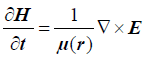
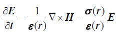
In order to study the field distribution of hexagonal pure silica glass PCF, we have used 2D finite difference time domain (FDTD) method. Considering the material is isotropic, linear, and lossless, the time dependent Maxwell’s equations can be written as:
 (1)
(1)
 (2)
(2)
E and H are electric field and magnetic field.
Where ε(r), μ(r) and σ(r) are permittivity, permeability and conductivity of the material and all are in the function of position.
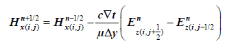
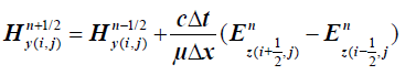
Eqns (1) and (2) can be discretized using Lee’s technique. Considering spatial and time discretization, eqns (1) and (2) can be written for TE polarization as follows:
 (3)
(3)
 (4)
(4)
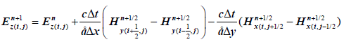 (5)
(5)
For stability, the time step:
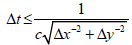 where Δt the time increment, c is the velocity of light, Δx be the lattice increment in x direction, Δy be the
lattice increment along y direction.
where Δt the time increment, c is the velocity of light, Δx be the lattice increment in x direction, Δy be the
lattice increment along y direction.
Considering eqns (3)-(5), we have calculated the field distribution of PCFs in TE polarization mode.
For a nonlinear optical waveguide having Kerr-type non-linearity related permittivity εr depends on electric field Ey and can be expressed as:
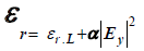 (6)
(6)
Where εr.L is the linear relative permittivity and α is the nonlinear co-efficient. A hybrid implicit FDTD method is used to simulate the field for 2D PCS with nonlinear rods. The overall stability of this hybrid FDTD scheme is determined by the stability in the linear medium regions. Consequently, nonlinearity in the structure does not affect stability and hence the grid size and time step.
The above numerical analysis is same for all nonlinear property of different design of PCF structure, whatever may be the background material.
The bend loss in photonic crystal fiber can be calculated as:
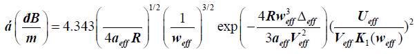 (7)
(7)
Where R=bend radius, aeff=effective mode field area, K1(Weff) is the modified Bessel first kind, Δeff=relative difference between the core and effective cladding indices, Veff=effective normalized frequency and Ueff is the another waveguide parameter respectively.
We have here considered the pure silica glass PCF structure with different values of structural parameter as compared to [11]. The bend loss property as well as the transmission loss on PCF structure is mainly focus in this article for optical communication purpose.
We purpose to design a theoretical model with a uniform defective layer to simulate the loss induced by surface imperfection in air holes. The cross-sectional view of such PCF structure is shown in Figure 1.

Figure 1: Defective layer PCF.
The drilling process will inevitably result in a defective glass layer with a surface rough, OH ions and other impurity particle. As diameter of air hole is in the order of micrometer and very thin defective layer, so it is very difficult to estimate the roughness of surface and thickness of defective layer in accurate way. For precise measurement, we assume that defective layer has uniform optical properties and extrinsic coefficient k. The complex refractive index of the defective layer is n-jk, where n is the refractive index of the silica glass PCF cladding structure and t is the thickness of defective layer. We purpose to assume that the PCF model has 60 air holes hexagonally arrangement, where‘d’ denotes hole diameter, ∧ is the separation between centres of adjacent core. The cladding diameter is chosen to be 126 μm and d/∧ value is set at more than 0.6. We focus on the existence of more than two propagation modes at a wavelength of 1.55 μm. The single mode operation condition is less than 0.43 [12]. As we concentrate on additional loss αh which results from the surface imperfection of the air holes and we ignore other factors like Rayleigh scattering and infrared absorption. We more concentrate and calculate the additional loss αh of FM and HOM at a wavelength of 1.55 μm by implementing 2D FDTD method. We consider the original thickness of defective layer in PCF structure preform is about 0.1 to 0.6 mm and the thickness of the air hole depends on type of drilling tool used. Actually the preform diameter is reduced during the drawing process, and hence the thickness of the defective layer t in a PCF structure is assumed to be in micrometer order. i.e. 2-3 order of magnitude larger than surface roughness of PCFs which fabricated by the stack and draw method estimated for atomic force microscope measurement [13]. As the glass tube used for capillary fabrication has been highly polished and dehydrated prior to the capillary drawing technique. So the defective layer made by stacks and draw method to be eliminated. The surface roughness remains in PCF structure fabricated by stack and draw method is due to the existence of surface capillary waves generated during the fiber drawing process. A part from this, we considered the absorption of OH ions in defective layer and also the roughness induced scattering. We set to t=1 μm including the diffusion length of OH ions [14] and k=3 x 10⁻⁹ as initial value of drilling perform and this k value is equivalent to transmission loss of 100 dB/km provided the entire PCF core has identical k value. So we investigated the additional loss αh using this initial value and agree with experimental result shown in Figure 2.

Figure 2: (a) αh Versus d/∧ where ∧=12.5 μm; (b) αh Versus ∧ where d/∧=0.7
We initially investigated the relation between αh and for a fixed value of ∧=12.5 μm. Figure 2a plots the variation between αh and d/∧ value.
The simulation result shows that the value of αh on both FM and HOM gradually increase with increase of d/Δ value from 0.5
to 1. These increases are more than 50% because of that when ∧ is constant and increasing  value. As a result the separation
between fiber core and the defective layer of innermost air holes decrease. It is observed that the value of αh for HOM is always
more than the FM due to the mode field area Aeff of HOM is nearly 21% larger than that of FM. Therefore HOM is more affected
than the FM. Similarity the Figure 2b plots the of αh versus ∧ at a constant value of d/ ∧=0.7. It is seen that the value of h for both
FM and HOM decrease while the value of ∧ increase from 12 to 17 μm and also observed both are decreased approx. by 50%
due to the power confinement in the core is more stronger when d/∧ is constant and ∧ increase [15]. Apart from these it concluded
that by suitably choosing a smaller the value d/∧ and a larger is the value ∧, as a result αh value reduced. However the effect
of optimizing the PCF structure is so limited because we have considered the other property like bend loss and mode field area.
In order to reduce the value of αh to a negligible level, the inner surface of PCF air holes should be considered. For treatment of
inner surface of air holes the parameter k and t must depend on it and hence we next investigated the loss dependence on these
parameters. The Figure 3a and 3b show that the variation between αh versus k and αh versus t respectively.
value. As a result the separation
between fiber core and the defective layer of innermost air holes decrease. It is observed that the value of αh for HOM is always
more than the FM due to the mode field area Aeff of HOM is nearly 21% larger than that of FM. Therefore HOM is more affected
than the FM. Similarity the Figure 2b plots the of αh versus ∧ at a constant value of d/ ∧=0.7. It is seen that the value of h for both
FM and HOM decrease while the value of ∧ increase from 12 to 17 μm and also observed both are decreased approx. by 50%
due to the power confinement in the core is more stronger when d/∧ is constant and ∧ increase [15]. Apart from these it concluded
that by suitably choosing a smaller the value d/∧ and a larger is the value ∧, as a result αh value reduced. However the effect
of optimizing the PCF structure is so limited because we have considered the other property like bend loss and mode field area.
In order to reduce the value of αh to a negligible level, the inner surface of PCF air holes should be considered. For treatment of
inner surface of air holes the parameter k and t must depend on it and hence we next investigated the loss dependence on these
parameters. The Figure 3a and 3b show that the variation between αh versus k and αh versus t respectively.

Figure 3: (a) αh Versus k.(t=1 μm); (b) αh Versus thickness t (where ∧=12.5 μm & d/∧=0.7).
The simulation result predicts that the value of αh almost linearly increase with increase the value of k for HOM. However in case of FM αh value slightly increase with increase of k value. As αh is a strong function of thickness ‘t’ of defective layer. So the variation of αh versus t graph signify that αh suddenly decrease for HOM and slightly decrease in case of FM as thickness increase from 0.5 to 2 μm. This result shows that by reducing the roughness of surface, contamination is a very simple and precise to reduce the value of αh. In fact the treatment of inner surface imperfection of air hole PCF is most useful and has an impact on αh.
The method of polishing is so effective that which influence the defective layer. It reduces the thickness of defective layer. For PCF having large number of air holes, this method is time consuming and very difficult to carry out completely. Furthermore we investigated the polished layer on αh value, while considering a proposed design PCF structure having 5 air hole ring with a suitable parameter ∧=12.5 μm, d/∧=0.7, k=3 x 10⁻⁹ respectively. Out of 5 air hole ring layer, the innermost air hole layer is in yellow next 2nd air hole ring is in green and the third layer is blue i.e shown in below Figure 4 where polishing is allowed to first layer only, the first and 2nd layer and three layers only.

Figure 4: The name of polished layer PCF.
We considered that t=1 μm of unpolished layer and t=0 for polished layer. Further we investigated the variation of αh value and the layer number with polishing and unpolished treatment. It is observed that, the αh values of FM and HOM are absolutely reduced to less than 10-5 to 10-4 dB/km by completely eliminating the defective layer (t=0) of first layer. But we have not shown the above result graphically. Similarly elimination of 2nd and 3rd defective layer which further reduce the of αh value. Apart from these, the method of polishing will immensely increase the risk of damage to the preform. As a result the transmission loss of proposed PCF reduced by eliminating the defective layer of the innermost layer.
We further optimized two PCF structure A & B of same background material having 5 air hole ring contained in it. The above preform elongated into 26 cm in diameter rod and classified into two pieces. The PCF A is drawn from the first piece without any treatment while 2nd piece was treated the inner surface which having 6 air hole contained in it. The 2nd piece of preform was washed and etched lightly to clean the inner surface of the air holes. Similarly the PCF B was drawn from the 2nd piece of preform under same drawing condition as PCF A.
The above Figure 5 is the cross-sectional view of PCF A and B. We are considering the key parameter like d/∧ value is equal to 0.78 in both PCF structure and lattice spacing of PCF ∧=13.4 μm i.e little layer than the PCF B (11.7 μm). PCF B has a little deform of their air holes as compared to PCF A. It is due to the fact that inner surface treatment enlarged the innermost air hole of the second preform and during the PCF drawing, structural deform takes place. This deformation of air hole in PCF structure may cause the measurement of the value d/∧ and ∧ in PCF B. while we observed that transmission loss is not occur, when the structure becomes deform.

Figure 5: The cross-sectional view of PCF-A & PCF-B.
Figure 6 shows the experimental set up for modal loss in which to evaluate the transmission loss of the HOM in more precisely. We reported from previous article that the planar light wave circuit through two mode coupler [x], where the light is coupled port-2 and then the input light beam in FM is changes to HOM and the output is from port-3. The model crosstalk of the planar light wave circuit was less than -15 dB. In order to know the first status of transmission mode, we investigated the near field pattern at the outer facet of the fiber at a 1.55 μm wavelength. The light is input from the port-2 and the near field pattern of the HOM is clearly observed as shown in Figure 6, while we further observed the transmission loss of FM and HOM respectively using 1.53 to 1.565 μm ranges.

Figure 6: Experiment setup for Modal loss &NFP calculation.
We next studied the experiment results. Figure 7a shows that, the loss of the HOM is more than that of FM. This loss mostly agrees with our theoretical observation as shown in Figure 2. Moreover the ratio of αh value for HOM and FM in Figure 2 is about 2.4 and we found that loss due to Rayleigh scattering and infrared radiation is 0.15 dB/km [16].

Figure 7: (a and b) Transmission loss versus wavelength in μm of PCF A&B.
The experiment value of the ratios is approximate  . This value is however smaller than that of our observed
value (2.4). This difference ratio value of αh is probably because we considered the same kind of uniform PCF structure for
the investigation. The ratio of αh values of the FM and HOM were decreased to less than 9% as compared to their original
value
. This value is however smaller than that of our observed
value (2.4). This difference ratio value of αh is probably because we considered the same kind of uniform PCF structure for
the investigation. The ratio of αh values of the FM and HOM were decreased to less than 9% as compared to their original
value  in the fabricated PCF by implementing polishing process only for the six innermost air holes. Furthermore it is
observed that the effect of inner surface treatment was limited as compared to our observed value. It is also probably because
we considered the complete elimination of defective layer in our observed value i.e the simulation result not shown here. The
experiment result of Figure 4 is rather similar to the result of Figure 3. As mentioned above, Figure 3 represent that the αh value
of FM and HOM fall to 10% of their original level by eliminating 70% of defective layer and hence we can’t completely eliminate the
defective layer in PCF B with inner surface treatment. So we observed further that, loss reduction is possible by optimizing both
air hole structure and inner surface treatment condition only.
in the fabricated PCF by implementing polishing process only for the six innermost air holes. Furthermore it is
observed that the effect of inner surface treatment was limited as compared to our observed value. It is also probably because
we considered the complete elimination of defective layer in our observed value i.e the simulation result not shown here. The
experiment result of Figure 4 is rather similar to the result of Figure 3. As mentioned above, Figure 3 represent that the αh value
of FM and HOM fall to 10% of their original level by eliminating 70% of defective layer and hence we can’t completely eliminate the
defective layer in PCF B with inner surface treatment. So we observed further that, loss reduction is possible by optimizing both
air hole structure and inner surface treatment condition only.
We reported both theoretically and experimentally that, the additional loss due to inner surface imperfection like contamination and surface roughness of the air holes of PCF. Furthermore our theoretical results based on a model with a defective layer which reveals that HOM has more loss due to air whole imperfection. In fact by reducing the inner surface imperfection of the six innermost air holes results the additional loss to be reduced to a negligible level. Apart from these, we also investigated few mode PCFs by introducing a suitable inner surface treatment for exactly six innermost air holes. It is observed that the transmission loss was considerably reduced using above investigation and the transmission loss is about 0.26 dB/km for FM and 0.37 dB/km for HOM at an operating wavelength of 1.55 μm.This results seem to be most important for optical communication system. From above result, it is also observed that, this theoretical result will be more suitable to realizing the few PCF modes whose loss is comparable to that of standard conventional fibre.