Keywords
|
| Automatic Vehicle Location Systems, GPS, GSM/GPRS, Arduino Uno Rev |
INTRODUCTION
|
| The fast growing field of Intelligent Transport Systems (ITS) spans from flight transport and traffic management to in-vehicle services like driver alert or vehicle monitoring. As a consequence, transportation information collection and communication plays a key role in all intelligent transport application [2]. One of the most important categories of ITS is the Automatic Vehicle Location (AVL) Systems. AVL is a means for determining the geographic location of a vehicle and transmitting this information to a point where it can be stored and used with certain software and database applications [3]. To do this, AVL systems uses a variety of hardware and software components. |
| This paper presents a Global Positioning System (GPS) based AVL system which comprises of three major components which are: GPS module, Global System for Mobile communication (GSM)/General Packet Radio Service (GPRS) module and a microcontroller; these components make up the In-Vehicle-Unit (IVU). Primarily, the GPS hardware employed in this research work was used to retrieve the vehicle location coordinates (the longitudes, latitudes and speed) while the GSM/GPRS module was used in transmitting the retrieved vehicle location coordinates to a web based server using the wireless network provided by the GSM/GPRS module. Arduino Uno Rev was used as the microcontroller and it acts as the central processing unit which was used to control the operations of the GPS and GSM/GPRS modules. Details of how the various modules work are enumerated in other sections. |
RELATED WORK
|
| Several works have been done in the field of ITS and most of them take advantage of the GPS to develop several applications which are used to make transportation service easier for both the transport management centres, drivers and passengers. In [1], four major categories of vehicle location technologies used in automatic vehicle monitoring and management systems were analysed, they are Signpost/Odometer, Ground-Based Radio Positioning (GBRP), Dead Reckoning and the GPS Based AVL System. In dead reckoning, calibration is needed on a continuous basis because the tyre dimensions change over time due to road conditions (for example, uneven roads, pot holes and hills), tire wear, and tire pressure [8]. The distance measured along a route may not correspond exactly to the path driven on any particular trip; as a consequence, the position will vary depending on distance driven. Though dead reckoning is inexpensive, accuracy degrades with distance travelled and it can also be corrupted by uneven road surfaces, steep hills or magnetic interference. In Signpost/Odometer-Based AVL System, a receiver is mounted on the bus while transmitters are placed along the bus route. In other instance, the transmitter can be placed on the bus and multiple receivers mounted along the route. Since the location of each signpost is known, the location of the bus at the time of passing the signpost is determined. The distance travelled since passing the last signpost as measured by the bus odometer is used to estimate the bus position along its route. This technology has a drawback because signposts are placed at fixed locations, thus, changes in bus routes could require the installation of additional signposts [7]. GBRP uses a low-frequency signal to cover a geographic area and the buses are located as they receive the signal. The time difference of signal reception is measured and is calibrated against a known position of remote stationary transmitters or receivers. Despite the simplicity of the system, overhead power lines or power substations can cause signal interference and signal reception is typically very poor in canyons [7]. |
| Due to the shortcomings of the other AVL technologies, GPS based AVLS system became the most popular system for new installations over the last few years [8], it uses the signals emitted from a network of 24 satellites, which are picked up by a receiver placed on-board the bus. The satellite system covers the whole world, thereby eliminating the need to place transmitters/receivers along any route. While the United States (US) military which oversees the satellite system has limited the accuracy of the system in the past, it is now allowing more accurate readings [5]. The accuracy and reasonable cost of GPS makes it the most appealing, though foliage, tall buildings and tunnels can temporarily block the satellite signal, the advent of differential GPS (DGPS) and assisted GPS (A-GPS) has eradicated these limitations to the nearest minimum [4]. Similarly, authors in [9] presented Wireless systems as a perfect communication channel for Intelligent Transportation Systems, they submitted that wireless communicationchannel is the basis of every effective and reliable traffic control and management application. While cellular-based communication through commercial carriers is widely used for online traffic management applications, they submitted that public agencies have also begun to consider other technologies, such as WiFi and WiMAX. [6] studied the privacy implications of location and tracking technologies and an outline of the familiar case of mobile phones, complemented by deeper assessments of road tolling and the surveillance of individual motor vehicles on the road was used as a basis for appreciation of the substantial threats that location technologies represent to free society. While different researchers have used different technologies to develop AVL systems, its correctness, reliability and efficiency remains performance metrics to improve on. Hence, this research work is premised along the provision of a more robust and effective GPS based AVL system. |
RESEARCH METHODOLOGY
|
| A. System Overview: |
| The developed AVLS comprises of two major segments, they are the hardware and the software segments. The hardware components are made up of the GPS, GSM/GPRS and the Microcontroller while the software components are the central server, the microcontroller programming and the user interface. The GPS module was primarily used to retrieve vehicle location information which are the longitudes, latitudes and the speed with which the vehicle is moving while the GSM/GPRS module was used to transmit the retrieved vehicle location information to a web based server. The microcontroller used is the Arduino Uno Rev which serves as the Central processing unit of the IVU; its main function is to coordinate the activities of the GPS and the GSM/GPRS module. The software segments include the Arduino Uno Rev programming, the user interface and the central server design and development. The hardware components must be programmed before they can communicate with each other while the users also need an interface that will enable them interacts with the developed AVLS. |
| B. `Hardware Consideration: |
| The components that make up the IVU are the GPS module, the GSM/GPRS module and the Arduino Uno Rev microcontroller. |
| ? The GPS Module |
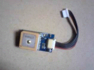
| The GPS module used as shown in Fig. 1 is a SUP500F Flash-based, Low-Power, High-Performance, 65 Channel Smart Antenna Module. Its -161dBm tracking sensitivity allows it to have wide continuous position coverage. Its high performance search engine is capable of testing 8,000,000 time-frequency hypotheses per second, offering industryleading signal acquisition and Time to First Fix (TTFF) speed. The GPS module receives signals from the satellite and determines the geographic location or co-ordinates of the vehicle. The GPS module can only receive but cannot transmit signal. |
| The GPS module was used to capture the actual location of the vehicle in real time. Since location information provided by the GPS is in numeric format, there is a need to process it into useful information that can be displayed by a beacon on the digital map. The GPS module can also provide information about the time of GPS fix (last reported location), status of GPS fix and number of satellite used to compute the current location information. For tracking purpose only location data is required for transmission. Other data provided by GPS receiver is used to determine the validity of location information. |
| ? The GSM/GPRS Module |
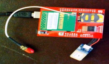
| The GSM/GPRS module used as shown in Fig. 2 is an ADH8086 Quad Band (850/900/1800/1900) GSM/GPRS module with embedded TCP/IP Stack, UDP/IP Stack, FTP and SMTP Client, SMS support and a SIM holder. It transmits GPRS data at a maximum of 85.6Kbit/s and it also support CSD data transmission up to 9600bit/s. Wireless network of the GSM/GPRS module was used to transmit the location coordinates received by the GPS module using direct TCP/IP connection. The retrieved vehicle location coordinates are transmitted to a central server through the GPRS network of the GSM/GPRS module. For data transmission over the GSM network, the GSM/GPRS module was also used. The GSM/GPRS module was used because it has a broad coverage and it is also cost effective rather than to deploy our own network for transmission of vehicle information. |
| ? Arduino Uno Rev Microcontroller |
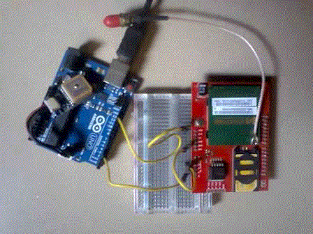
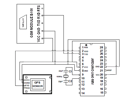
| Arduino Uno Rev 3 was used as the Microcontroller. It served as the central processing unit for the In-Vehicle unit and it controls all its operations. The microcontroller needs instructions to operate the whole system, these instructions were written to the microcontroller’s flash memory using C# programming language. It reads the software instruction by instruction and performs the action as required by the instruction. The Arduino Uno Rev consists of an Atmel 8-bit AVR microcontroller with complementary components to facilitate programming and incorporation into other circuits, it was programmed via USB implemented using USB-to-serial adapter chips such as the FTDI FT232. Fig. 3 shows how the Arduino Uno Rev 3 was interfaced with the GPS and GSM module. |
| ? Power Consideration |
| The Arduino microcontroller was initially powered by connecting it to a laptop using a Universal Serial Bus (USB) cable but when it was to be installed in the vehicle it was connected to a rechargeable battery that supplies a voltage of 5v. The developed system was later connected to the vehicle battery so that its battery could be charged while in use and when exhausted. The rechargeable battery used can work for six hours on its own and this is possible because the Arduino. |
SOFTWARE DESIGN CONSIDERATION
|
| The hardware modules cannot communicate with each other except they are programmed to do so; this is one of the benefits of the microcontroller used as it can be programmed using C# programming language. |
| The hardware modules cannot communicate with each other except they are programmed to do so; this is one of the benefits of the microcontroller used as it can be programmed using C# programming language. |
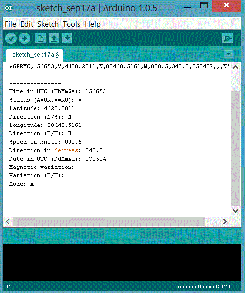
| The Arduino Uno Rev microcontroller was programmed using C# programming language, as a result of itsprogrammability, the activities of the GPS and the GSM/GPRS modules canbecoordinated. Figure 4 shows the Arduino Uno Rev programming interfacewith a snippet of code used to test the GPS module. |
| ? The Web Based Server |
| The web based server functions as the central database and is compliant with ASP.NET Internet Information server (IIS) which is a standard for web based services. The number of vehicles with the In-Vehicle Units (IVU) was not fixed therefore the server was designed in such a way that it can manage and distinguish all information received from all IVU installed in different vehicles. The server maintains a database of all the vehicle routes, the buses that ply on the routes, the stops along each route etc. It also stores static information such as the vehicle model and plate number, vehicle location history and authorized users. Dynamic information such as vehicle speed and distance covered, estimated time of arrival and geocoded address, available vehicle and their respective routes and updates were also saved into the central database. The web based server also serve as a host to internet web pages and a digital map which allows administrators to view the location of vehicles in real time. The central database was designed in such a way that its content can be accessed and modified by authorized users using a web interface. |
| ? Web Based User Interface |
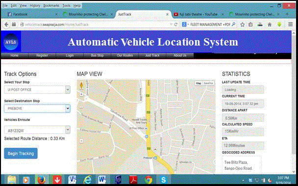
| The web based user interface as shown in Fig. 5 was created in ASP.NET programming platform using C# Programming Language. This gives administrators access to the digital and dynamic map being hosted on the web based server. The digital map is dynamic in the sense that whenever the location of the vehicle being viewed changes, the change in location is being automatically shown on the map. This will enable transport management centres to interact with vehicles that have the IVU installed in them. Since the web based user interface will be accessible over the internet, its access was restricted to authorized users only. Therefore, information about all users of the system was stored in the central database. |
THE SYSTEM CONSTRUCTION
|
| The construction of the system was done in phases viz: Assembling, Soldering and Casing. The components were first assembled together on a Vero board and tested according to the circuit diagram of the design shown in Fig. 6. After it has been confirmed that the components are communicating with each other, they were soldered together on a printed circuit board. The complete system was now housed in an iron case. Holes were made on the case using the drilling machine and the cases with the circuit were joined together with the use of bolts and nuts. |
| ? How the System Works |
| The Arduino Uno Rev microcontroller with the GPS and the GSM/GPRS module make up the In-Vehicle Unit (IVU) that was built into the vehicle. Once installed in a vehicle and powered, the IVU has been programmed to retrieve and transmit the location coordinates of the vehicle concurrently, this location information will be forwarded to the web server through a wireless network provided by the GSM/GPRS module. Each vehicle with the IVU has a unique identification number so that the central server will be able to differentiate the vehicle location information being sent by a particular vehicle. Transport management centres can use the web user interface to interact with each vehicle hosting the IVU thereby, monitoring their vehicles. |
| ? Testing the Developed System |
| The developed AVLS was tested as units before being tested as a whole. The GPS module which has been mounted on the microcontroller was connected to a laptop through a USB cable. The microcontroller was then programmed to initiate a request for location, on receipt of the requested location information as shown in Fig. 4, it was confirmed that the GPS module was working properly. The GPS module which transmits information in serial Transistor–Transistor Logic (TTL) format was connected to pin 0 (RX) of the Arduino Uno Microcontroller as shown in Fig. 6. |
| The GSM/GPRS Module was also connected to microcontroller already hosting the GPS module. The microcontroller was once more programmed to initiate an action that will cause the GPS module to retrieve the vehicle location and also to initiate the GSM/GPRS module to send the retrieved location to a web based server, on receipt of the transmitted location information, it was ascertained that the system works perfectly. |
CONCLUSION AND FUTURE WORK
|
| This paper has successfully presented a functional and a low power consuming AVLS that can be installed in any vehicle primarily for retrieving its location coordinates and speed. This information will avail transport management centres the opportunity to monitor their vehicles in real time whilst monitoring the drivers driving the vehicles. The application area of the developed AVLS depends on the foresight and need of the transport management centres as its use is quite enormous. It is highly recommended that transport authorities will explore the enormous benefits hidden in the freely available global positioning system as the knowledge of where a vehicle is in real time can serve a basis for many innovative ideas that can change the face of public transportation system and make it a better alternative to private transport. |
Figures at a glance
|
 |
 |
 |
| Figure 1 |
Figure 2 |
Figure 3 |
|
 |
 |
 |
| Figure 4 |
Figure 5 |
Figure 6 |
|
References
|
- Christine, M. J. and Edward, L. T., “Automatic Vehicle Location Successful Transit Applications: A Cross-Cutting Study”, ITS Joint Program Office, Federal Highway Administration, United States, 2002.
- David, T., Daniele, M., L. and Francesco, C., “Using Wireless Sensor Networks to Support Intelligent Transportation Systems, Journal of Ad Hoc Networks, Vol. 8, No. 5, pp. 462-473, 2010.
- Daniel, P., “Automated Vehicle Location using Global Positioning Systems for First Responders”, Institute for Information Technology Applications Technical Report Series, 2354 Fairchild Drive, Suite 4L35F, USAF Academy CO 80840-6258, 2008.
- Richard, J. Z., Edward, A. B., Zhong-Ren, P. and Simi, O., “State of the Art in Automatic Vehicle Location Systems”,Center for Urban Transportation Studies at University of Wisconsin – Milwaukee, 2008.
- Ravi, S., “Applications of Advanced Technologies to Transportation Systems in Indian”, International Journal of Earth Sciences and Engineering (IJESE) ISSN 0974-5904, Vol. 4, No. 6, pp. 394-397, 2011.
- Roger, C.andMarcus, W., “You are where you’ve been: the privacy implications of location and tracking technologies”, Journal of Location Based Services,Special Issue: The Social and behavioralImplications of Location-Based Services, Vol. 5, No. 4, pp.138-155, 2011.
- Srinivas, P., Venkata, D., Shah, I., Pooya, N. and Zahid, R., “Commercial Remote Sensing and Spatial Information (CRS & SI) Technologies for Reliable Transportation Systems”, Draft Synthesis Report on Literature Review Submitted to Research and Innovative Technology Administration (RITA), United States Department of Transportation, 1200 New Jersey Avenue, S.E., Room # E33-467 Washington, DC 20590, 2013.
- Watje, J.M., Denis, S. andRobert, S., “Vehicle Location Technologies in Automatic Vehicle Monitoring and Management Systems. IVHS Journal, Vol. 1, No. 3, pp. 295-303, 2007.
- Yan, Z., Glenn, H. E., Mashrur, C., Kuang-Ching, W.andRyan, F., “Wireless Communication Alternatives for Intelligent Transportation Systems: A Case Study”, Journal of Intelligent Transportation Systems: Technology, Planning, and Operations , Vol. 15, No. 3, pp. 147-160, 2011.
|