Research & Reviews: Journal of Pure and Applied Physics
ISSN: 2320-2459
ISSN: 2320-2459
Umeh CD1*, Agwu KK2 and Okoye CI1
1Department of Physics and Astronomy, University of Nigeria, Nsukka, Nigeria
2Department of Radiography and Radiological Sciences, University of Nigeria, Nsukka, Nigeria
Received Date: 19/08/2018; Accepted Date: 10/09/2018; Published Date: 20/09/2018
Visit for more related articles at Research & Reviews: Journal of Pure and Applied Physics
Nigeria has over ten million tons of lead predominantly situated in the Abakaliki field in the lower benue trough. The authors decided to embark on a study to document its shielding strength towards X ray beam in the diagnostic energy range. Measurements of narrow and broad beam attenuations were made across different cut out thicknesses. Our results show that the linear attenuation coefficient is lower when compared to the value in the NIST table; 42% for N100KeV and 18% for N120KeV. These authors believe might be due to impurities because of the increased weight trying to undermine its shielding capacity or from the X ray factors. However, it could still give adequate shielding performance with a minimum thickness of 4mm following broad beam attenuation.
Typical materials for shielding walls, floor and ceiling are lead, concrete and barite [1]. Lead is widely distributed all over the world in form of its sulphide (PbS) known as Galena. It ranks 36th in natural abundance among elements in the earth’s crust. Nigeria’s most important lead-zinc deposit is the Abakaliki field which is made up of four lodes: Ishiagu, Enyigba, Ameki and Ameri in the lower Benue trough [2]. A large deposit of over 20 million tons of complex sulphide minerals is available in Nigeria especially in Ishiagu, Ebonyi state [3]. It is estimated that Nigeria has over ten million tons of lead ore deposit predominantly found in Zamfara, Niger and Ebonyi states [4]. Lead has several properties that make it advantageous to use alongside its commonness, high density, low melting point, ductility, and relatively inertness against oxygen attack. Lead minerals are easy to mine and are easier to extract from its ores than many other metals.
In Nigeria, there have been lots of challenges in compliance to radiation standards in diagnostic health centers. Using imported lead shields and ordinary thick concrete seams to ameliorate; but still has its toll on the economy. Locally mined lead which could be used for wall designs is at varying stages of characterization. Olubambi [3] did a mineralogical characterization of Ishiagu, Ebonyi state, Nigeria’s complex sulphide ore where their study provided relevant mineralogical information on which the processing of the ore could be easily achieved. Onyedika [5] made a detailed mineralogical and elemental characterization of this deposit using XRD, SEM-EDX and ICP -DES based mapping techniques where their results show that the most dominant and valuable metal is lead. (Pb=95.02% mass fraction). Egwuonwu [6] combined Galena samples from Ishiagu, Ebonyi state with concrete and was molded into different densities to ascertain its attenuating capacity to EM radiation. Their results show that a typical Ishiagu galena concrete of about 2.80 g/cm3 has the capacity of shielding visible blue light with about 2.51 mm TVL and 0.81 mm HVL. Their result, however, did not identify the attenuating strength to be either galena or concrete. The works of Doyema [7] and Geoffrey [8] reported on the severe hazards of lead deposits in Northern Nigeria due to illegal mining. Simba [9] made a case for an environmental remediation for addressing childhood lead poisoning in Northern Nigeria.
No literature has provided us with the attenuating strength of deposit in a relative purified form to e diagnostic energy range and this is the vacuum we intend to fill. We took a survey of all the Radiotherapy centers across the federation and found out that the lead plaster used for its wall designs were all imported from South Africa. The wall designs of some of the diagnostic centers where our locally mined lead was used; its shielding strength were based on mere assumptions. The use of kilovoltage X-ray beams is increasing for radiation therapy in some countries and forms an integral part of radiation treatment due to its low cost, relativ e free operation and superior outcomes [10,11]. Currently, the country intends to build more Radiotherapy centers across the federation. Available broad beam data are found to be unsatisfactory and according to Hoff [12]; the adequate characterization of a shielding material is important for supporting efficient radiation shielding design processes. The authors believe that the result of this study will give basic information on the radiation shielding capacity of the lead sample deposit found in Ebonyi state. Radiation shielding and protection barrier calculation for members of the public and radiation workers is directly related to the accuracy of published and available data [13].
Location and Geology of Ishiagu, Ebonyi State
Ishiagu is bounded by longitude 7°29’-7°35’E and latitudes 5°43’-5°51’N. The relief of Ishiagu the mining site is low-lying and undulating. The rocks are excessively fractured, folded and faulted (Figure 1). It is exclusively fissure filling and distinctively patterned in the NW-SE fractures and gangue minerals [6].

Figure 1: Map of Nigeria showing the Benue trough locations [3].
The site comprises of sand, lenses of sandstone and limestone, shales’s with fine grained micaceous sandstones and mudstones that are Albian in age. Galena which often occurs as fine aggregates and sphalerite are the dominant constituents of the veins [6,14]. The distribution of lead, zinc, and other heavy elements in Ishiagu is due to their occurrence in veins and veinlets. Galena occurs in mineralized veins, mine dumps, folded shales, the Asu River shales and the minor basic intrusive [6,15].
Samples of lead were collected from the mining site at Ishiagu, Ebonyi state. The samples were purified via blast furnace process before being molded into slabs for onward X ray beam transmission under the narrow and broad beam geometries.
Narrow and Broad Beam Attenuation
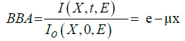
These measurements were done with a comet MXR-320 X-ray tube installed at the Institute of Radiation Protection, University of Ibadan. The set-up sketch is shown in Figure 2. The Medium Exposure Standards (MEES) was used to determine the relative attenuation of a variety of thicknesses of attenuating material in the filter position. Attenuation is defined as the ratio of intensity with and without attenuating material
I=Ioe-μx (1)

Figure 2: Experimental set up of our narrow and broad beam attenuation measurement. There was the presence of collimator during broad beam measurement.
Where I and I0 are intensity with and without attenuating material thickness, x in the beam. μ is the linear attenuation coefficient. Details of the beam qualities and Half-Value Layer are shown in Table 1 while the effective transmission of the radiation qualities is shown in Table 2. In our experimental set up, μ is determined from narrow beam geometry set up. X ray beam from the source was collimated by using a cylindrical lead block with a central hole of diameter 1 cm. The transmitted beam was also collimated using a similar lead cylinder. We considered both narrow and broad beam attenuation measurements because according to Das [10], narrow beam data should not be used for organ shielding. BBA data are desired for clinical use; though subject and dependent on the measuring conditions. The lead sample was checked for the presence of radioactivity and no contributory signal above background radiation was detected.
Table 1: Radiation quality used in the study: N for Narrow beam and B for Broad Beam
| B115 | N115 | B140 | N140 | |
|---|---|---|---|---|
| Mean Kev | B100 | N100 | B120 | N120 |
| Filtration (mm) | 5.5Al | 4.0Cu | 6.51Al | 5.0Cu |
| 0.9Sn | 1.1Sn | |||
| HVL(mm) | 4.8Al | 1.6Cu | 6.04Al | 1.75Cu |
Table 2: Effective transmission (%) of our radiation beam.
| Thicknesses/mm | Diagnostic energy range | |||
|---|---|---|---|---|
| B100 KeV | N100 KeV | B120 KeV | N120 KeV | |
| 2 | 1.0 × 10⁻² | 6.0 × 10⁻¹ | 7.0 × 10⁻¹ | 8.0 × 10⁻¹ |
| 3 | 8.5 × 10⁻³ | 5.0 × 10⁻² | 1.0 × 10⁻² | 6.0 × 10⁻² |
| 4 | 1.0 × 10⁻⁴ | 7.0 × 10⁻³ | 5.5 × 10⁻³ | 9.0 × 10⁻³ |
| 5 | 4.0 × 10⁻⁶ | 9.0 × 10⁻⁶ | 9.0 × 10⁻⁶ | 6.0 × 10⁻⁵ |
| 6 | 1.0 × 10⁻⁸ | 7.0 × 10⁻⁸ | 5.0 × 10⁻⁸ | 1.0 × 10⁻⁷ |
Dosimetry codes do not provide any guidelines on clinical matters such as broad beam attenuation (BBA) data [10]. In an ideal broad beam geometry; every scattered or secondary uncharged particle/photon energy in addition to the transmitted photon energy strike the detector, but only if generated in the attenuator by a primary particle on its way to the detector or by a secondary charged particle resulting from such a primary one [16]. When detected by our chamber at a field size of 10 cm2 × 10 cm2; it approximates to the real-life picture of the BBA strength of our material
 (2)
(2)
The beam energies used in this study were 100 KeV and 120 KeV. The purified lead attenuator of 10 × 10 cm2 with precise thicknesses of 2 mm to 6 mm were designed using the fully automated lead sheet rolling mill (87113) and weighted. The detector with the set-up is a 1¾ “2” NaI(Ti) detector coupled to a ten-photomultiplier tube in an integral assembly supplied by Broch Technologies. The output pulses from the PMT anode were fed to the main linear amplifier through a pre-amplifier. Spectra were recorded using a Nucleonix 4k MCA. For each attenuator thickness and energy, five measurements were made to take average. In the narrow beam attenuation, the total counts in the various energy lines were determined and plotted on a semi logarithmic plot as a function of attenuator thickness. The slopes of the resulting straight lines were evaluated by the linear equation. For the BBA; exponential transmission curves were displayed for a better picture of the attenuating strength of each attenuator.
Half Value Layer (HVL) and Tenth Value Layer (TVL)
Half Value Layer (HVL) is the thickness of our lead sample that will reduce the intensity of the beam to half of its initial value.
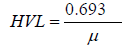 (3)
(3)
Tenth Value Layer (TVL) is analogous to HVL except that it is the thickness of our lead sample that will reduce the intensity of the beam to one tenth of each initial value. We will determine this for each energy using
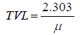
The TVL is often used in x ray room shielding design calculation [17].
Lead Thickness
The lead cut-out is placed in the skin surface to shape the field size. The thickness of the lead pieces is either taken from published data or from direct measurement [10]. In our own case, we made a direct measurement. This thickness could also be used wall design for shielding purposes.
These values of air kerma transmission were used for determining the linear attenuation coefficient (Figures 3 and 4) and the attenuating capacity of our lead sample under the BBA. The density of the sample is 12.5 g/cm3. The N100 KeV gave a linear attenuation of 40 cm-1 and the N120 KeV has a linear attenuation of 39 cm-1 . The mass attenuation coefficient given from the National Institute of Standards and Technology (NIST) is 5.549 cm2/g for N100 KeV and 3.8 cm2/g for N120 KeV [18]. Our sample gave a value of 3.2 cm2/g and 3.12 for both N100 KeV and N120 KeV respectively given a percentage deviation of 42% and 18% respectively (Tables 3 and 4). This deviation will perhaps require that our sample should further undergo physical and chemical analysis. Alternatively, Tsalafoutas [19] and Rossi [20] are of the view that primary transmission and HVLs from different author do not generally agree well. As stated by Rossi [20], these differences could be due to generator wave forms, X-ray beam HVL, irradiation field size and segment of the attenuation curve used to calculate the high attenuation HVL. So, comparison of attenuating properties of different materials from different authors could lead to misleading conclusions. The corresponding HVL and Tenth Value Layer (TVL) are 0.017 cm and 0.058 cm respectively (from eqns. (3) and (4)) for the N100 KeV; while that of N120 KeV is 0.018 cm and 0.059 cm (Figures 5 and 6).

Figure 3: Linear Attenuation coefficient for N100 KeV.

Figure 4: Linear Attenuation coefficient for N120 KeV.

Figure 5: BBA of 100 KeV.

Figure 6: BBA of 120 KeV.
Table 3: Attenuating parameters.
| KeV | µ/cm-1 | HVL/cm | TVL/cm |
|---|---|---|---|
| N100 | 40 | 0.017 | 0.058 |
| N120 | 39 | 0.018 | 0.059 |
Table 4: Mass attenuation coefficient (cm2/g) in comparison with NIST values.
| KeV | Our sample | NIST | Deviation |
|---|---|---|---|
| N100 | 3.2 | 5.549 | 42% |
| N120 | 3.12 | 3.8 | 18% |
The broad beam attenuation is used to determine the attenuating capacity of the different cut out thicknesses. The sample thicknesses seem to have a similar capacity to 100 KeV and 120 KeV. Thicknesses of 2 and 3 mm were not adequate for ideal shielding; while thicknesses of 4 mm and above give better shielding performance.
Lead ore sample deposit in Ishiagu, Ebonyi state, South Eastern Nigeria has a weaker attenuating capacity when compared to Standard theoretical value; but could still be used for radiation shielding in the diagnostic imaging range. It should still undergo further physical and chemical characterization to account for the deviation of the its linear attenuation coefficients values from the theoretical value given in NIST table or from experimentation from other authors when performed using the same X ray factors. The authors believe that certain impurities or other compounds might be present within the sample which tend to undermine its shielding strength. For both 100 KeV and 120 KeV, a thickness of 4 mm is adequate to provide the required shielding. Increasing the thickness further could warrant to unnecessary cost. This thickness could also be used for shielding purposes in the diagnostic imaging energy range which is common to most diagnostic centers in Nigeria. The values of μ, TVL, and HVL in our study should serve as a data base for the use of this sample.
We would like to thank the Tertiary Education Task Fund (TETFUND) for funding this work and the Institute of Radiation Protection, University of Ibadan for their technical support