Research & Reviews: Journal of Pure and Applied Physics
ISSN: 2320-2459
ISSN: 2320-2459
Hriday Dath*, S. Kannan, V. N. Radhika
Department of Physics, ISRO Inertial Systems Unit, Thiruvananthapuram, 69013, Kerala, India
Received: 27-Apr-2023, Manuscript No. JPAP-23-97152; Editor assigned: 28-Apr-2023, PreQC No. JPAP-23-97152 (PQ); Reviewed: 12-May-2023, QC No. JPAP-23-97152; Revised: 19-May-2023, Manuscript No. JPAP-23-97152 (R); Published: 26-May-2023, DOI: 10.4172/2320-2459.11.2.002
Citation: Dath H, et al. Sub-Doppler Cooling of 87Rb for Transportable Gravimeter. Res Rev J Pure Appl Phys. 2023;11:002.
Copyright: © 2023 Dath H, et al. This is an open-access article distributed under the terms of the Creative Commons Attribution License, which permits unrestricted use, distribution, and reproduction in any medium, provided the original author and source are credited.
Visit for more related articles at Research & Reviews: Journal of Pure and Applied Physics
We have demonstrated the sub-Doppler cooling of 87Rb in a 3D MOT as a first step toward realizing a cold-atom mobile gravimeter. A com-pact Ti-UHV chamber is designed for this purpose and has achieved sub-Doppler cooling of 87Rb atoms to a temperature of ~16 µK through a multistage cooling sequence. Sub-Doppler laser cooling requires optical pumping among differently light-shifted ground-state sublevels. We describe the study and characterization of the sub-Doppler cooling in a real MOT with σ+ − σ− beam configuration. A theoretical overview is provided, and the experimental setup is described in detail.
87Rb atoms; Gravimeter; Configuration; Magnetometers; Quantum optics; Velocity
Extensive research has been done on laser cooling, trapping of neutral atoms to use as a compact, reliable, and portable system for applications in quantum optics, metrology, and sensor development [1–6]. This technique utilizes very low velocity atoms that are generated and trapped in a controlled environment and has proven its application in atomic clocks, magnetometers, etc [7-10]. The motivation behind our approach is to develop and master laser cooling techniques to generate a sufficiently cooled atom cloud of 87Rb as a proof mass for building atom interferometry based gravimeters.
Einstein interpreted atoms as oscillators that react to resonant photons by change of momentum and internal energy [11]. It is well established that in a resonant light field, atoms undergo directed momentum transfer [12]. By careful adjustments of laser beams, momentum transfer to neutral atoms to reduce their velocity and trap their free movement is possible. Magneto Optical Trap (MOT) [13] is a relatively simple and widely used technique that allows the simultaneous cooling and trapping of atoms from the room temperature thermal background. A MOT of neutral atoms is generated by using red detuned counter-propagating laser beams in three axes and an Anti-Helmholtz magnetic coil.
The cold atom technology has matured as a result of nearly three decades of trail-blazing efforts by theoretical and experimental physicists [14–20]. Over the years, numerous cooling techniques were developed for attaining even lower temperature regimes. The likes of evaporative cooling, gray molasses cooling, Raman sideband cooling are techniques used to harness low temperatures for generating Bose-Einstein Condensate (BEC) [21-27].
The initiative from ISRO Inertial Systems Unit (IISU) is to develop cold atom-based inertial sensors for the proof of concept demonstration in the laboratory. In the present work, we discuss the experimental configuration of MOT formation and atom cloud generation in the laboratory setup designed for transportable avimeters. The paper is organized as follows; in sec. 2, we briefly discuss the theory of atom cooling and trapping with more emphasis on the cooling in a real MOT. The cooling scheme and optical design employed to achieve the low temperature in the laboratory are elaborated in sec. 3, we present the characterization of the achieved cold atom cloud parameters (the number of atoms and temperature of the proof mass) in sec. 4, and in sec. 5, and we conclude the paper.
Theory
In this section, we briefly discuss the theory of atom cooling and trapping before proceeding with the experimental procedure and results in the upcoming sections.
Since photons carry momentum, their interaction with neutral atoms involves the transfer of momentum through absorption and emission. The force (scattering) transmitted to the atoms from absorption followed by spontaneous emission is [28].
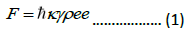
where Ãâçk is the photon’s momentum, γ is the decay rate, and ρee is the probability for the atoms to be in the excited state. This force will facilitate the reduction of atomic velocity and thereby cool the atoms but cannot use for trapping. However, increasing the intensity beyond a certain limit increases the rate of stimulated emission and hence will not result in a higher F. We thus go for a scenario in which an atom experiences a standing wave, i.e., a pair of counter-propagating laser beams. The interference of these beams produces an amplitude gradient, and the resulting spatially modulated light shift produces a conservative force (Dipole Force). This force can be used to trap, unlike the scattering force. The counter-propagating beams that we apply are red detuned concerning a stationary atom. A laser beam resonant with an atomic transition will exert maximum force on low-velocity atoms, and ‘heating’ will occur. Red detuned counter-propagating beams results in more scattering event and a velocity dependent damping force for the atom. This state is the “optical molasses”, and its three-dimensional extension is well-known [29].
Atom confinement or trap is the beam configuration such that the atomic motion is confined in a small known region. From optical Earnshaw theorem, we know a stable trap is impossible from dissipative forces [30]. Thus we utilize external inhomogeneous magnetic fields and radiative selection rules to create the most widely used trap for neutral atoms called Magneto-Optical Trap (MOT). In MOT, we use a linearly inhomogeneous magnetic field ((B(z) α z)) created using a pair of Anti-Helmholtz coils (uniform gradient in all directions but with different slopes). 3-D MOT consists of six beams in three orthogonal directions with σ+ (âÃËÃâ m=+1 transitions) and σ− (âÃËÃâ m=-1 transitions) polarizations in counter-propagating configuration. Because of the Zeeman shift of the energy levels and the polarization configuration, the atoms away from the center (B(z)=0 at the center) experience more scattering from one beam in the counter-propagating pair and are driven towards the center. As the beams are red detuned from the atomic resonance, cooling and trapping are simultaneously possible in MOT.
Due to the discrete size of momentum steps and the recoils in a random direction that atoms undergo with each absorption and emission, cooling to T=0 will not happen. At the steady state, the heating and cooling rate are equal, and this steady state temperature (TD) is called the doppler cooling limit. For 87Rb TD ≈ 140 µK. Sub-Doppler cooling is the reduction of atom temperature below this Doppler limit. The detailed theory and various schemes for sub-Doppler cooling are well explained in [28]. In the case of MOT with six beams, there are several non-trivial polarization formations [31]. Hence the theory introduced for sub-doppler cooling will seem invalid, but it has been found that there is always a region with a suitable beam configuration that allows sub-doppler cooling with one or more of the schemes mentioned in [32].
Experimental setup
The laboratory setup consists of vacuum subsystems, an electronic rack, an optical module, and a data acquisition/processing module. The entire system is placed on a vibration isolation platform to eliminate the effects of external disturbances. Our vacuum system consists of a titanium-made ultra-high vacuum chamber, Two Sputter Ion Pumps (SIPs), A Non-Evaporable Getter (NEG) pump and two vacuum gauges. Material for vacuum chamber was chosen due to its lower magnetic susceptibility compared to stainless steel [33–35]. The schematic of the UHV chamber is shown in Figure 1. The portable pumping station containing a Rotary Pump (RP) and a Turbo Molecular Pump (TMP) is connected to the chamber when required and disconnected after achieving the desired pressure using an isolation valve. This vacuum system helps in quickly reaching and holding the ultra-high vacuum condition and eliminates the bulky RP and TMP from the portable unit. SIPs (SAES) are always kept in the ON state to maintain the vacuum. The Rb dispenser (SAES 5G0125) is placed inside the chamber and activated by an electrical feed-through. The released atomic vapor deposits a coating on the inner walls of the UHV chamber and equilibrates at 10-9 mbar.

Figure 1: The portion of the Ti chamber where the cloud formation takes place.
By cautious design and fabrication, we ensure that the UHV chamber view ports are in orthogonal orientation, enabling all six cooling beams to enter and access the MOT center. The collimators are attached to the viewport using specially designed clamps to align all the cooling beams. The MOT coils are attached to the chamber with recessed flanges that align themselves with the horizontal cooling axis. A power supply drives the required current to generate the trapping quadrupole magnetic field (∂B/∂z=12 G/cm). The laser beams are generated from two laser sources (Toptica DL pro) and one laser amplifier (BoosTA pro). Laser frequency locking is carried out using the saturation absorption spectroscopy (SAS) setup and lock-in amplifier. The laser beams are split, redirected, and modulated using an acousto-optic modulator (AOM, MT80-B30A1 of AA Opto-Electronic) in a double pass configuration. A magnetic coil shutter is designed and integrated in the experimental setup for temperature characterization. These are recombined and coupled into the optical fiber using appropriate optical components shown in Figure 2.

Figure 2: The schematic diagram for beam generation for cooling atoms in MOT.
Intensities of all six cooling beams are equalized before applying to the chamber. 87Rb has a single electron in the 5s shell, and the central wavelength of the D2 line (52S1/2 → 52P3/2) is 780.2 nm. The cooling transition for 87Rb is the cycling transition from 52S1/2 F=2 → 52P3/2 F=3 [36]. To produce the Doppler force, the cooling laser is 18 MHz red detuned from the above- mentioned cycling transition. As a result, a finite probability for the transition 52S1/2 F=2 → 52P3/2 F=2 exists, and then the atoms can relax to F=1 and would not take part in cooling. To overcome this, we use the repumping laser (52S1/2 F=1 → 52P3/2 F=2). The atoms undergoing this repumping transition can de-excite to 52S1/2 F=2 and can participate in the cooling process. Figures 3A and 3B depicts the photograph of a cloud viewed using an IR camera (pco.pixelfly).

Figure 3: Cold atom cloud images. (a) Image captured in infrared camera through a viewport and its false-color image after background subtraction. (b) Intensity histogram of atom cloud.
Experimental sequence
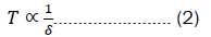
The steps we carry out for the cooling sequence is given in Table 1. The cycle time for one measurement is 5 s, of which 4 s is to load the atoms into MOT and the remaining time for molasses, free expansion followed by the detection. Here atom recapture is not possible for temperature measurement due to the limitation of the camera read-out time. We have not focused on minimizing the cycle time as our target was to systematically characterize and optimize the cooling. Pulse adjustments were performed to obtain the best possible temperature, and the scheme we followed is in Figure 4. Note that during the molasses stage, we have ramped down the intensity and increased the cooling detuning. This is attributed to the equilibrium condition of the sub-Doppler cooling mechanism (Sisyphus cooling), where I is the laser intensity, and δ is the detuning. We can utilize the higher laser intensities as long as the heating effects caused by it are not dominant.
| Time | Process |
|---|---|
| 0 to 4 s | Load MOT |
| Next 13 ms | Optical Molasses |
| Next 1 to 100 ms | Cloud free expansion |
| Next 1 ms | Detection |
Table 1. Steps in cooling sequence for temperature measurement.

Figure 4: Experiment sequence. Cooling, repumping beam intensities, and detuning are independently controlled during the cooling stage. By changing the free expansion time from 1 ms to 100 ms, the temperature of the cloud is measured.
Atom number estimation
The number of atoms getting trapped is estimated from the scattering rate [36]. The fluorescence images of atom cloud are acquired using a CCD camera and the exposure time and efficiency are to be taken to account for the calculations. The number of atoms Natoms is;
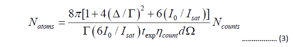
where I0 is the intensity of one cooling beam, Ncounts is the integrated number of counts on CCD, texp is the camera exposure time, ηcount is the CCD efficiency (counts/photons), and dâÃâæ is the solid angle of light collected by the camera.
First the atom cloud is released from the trap, and the cloud is imaged for measurement. The image processing consists of estimating the integrated number of counts estimated by the CCD. By applying Eq. (3), the number of atoms trapped in the cloud is obtained and is ~ 4 × 10⁷.
Temperature calculation
The efficiency of the cooling scheme is assessed through characterizing the cold atom ensemble by calculating the temperature. Subsequent to numerous cycles of tuning and adjusting the laser beam parameters followed by measuring the cloud temperature, the optimum cooling scheme has been finalized as depicted in Figure 4.
The temperature is calculated through the time of flight method, where the cold atom cloud is released from the magnetic trap. The released atomic ensemble will freely evolve in gravity [37,38]. The inherent internal energy of atoms in an ensemble manifests as an increase in cloud size as time progresses. The rate of expansion of the cloud is directly proportional to its temperature according to the equation;
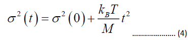
Where σ is the standard deviation of the gaussian fitted to cloud histogram at time t, kB is Boltzmann constant, M is the mass of the atom, and T is the temperature in kelvin.
To characterize, we capture the cloud images in different free expansion time duration. For each time, ten images are captured and averaged. Through image processing, the intensity histogram of the atom cloud is measured, and its variance (σ2) is calculated. By plotting σ2 vs t2 data points and performing a linear fit, the temperature of the cloud is obtained from the slope of the fit shown in Figure 5.

Figure 5: Free expansion plot to calculate the temperature. The x and y temperature obtained after the multi-step molasses stage are 18 μK and 14 μK respectively. 
In our study, we show that using simple MOT, the cooling and trapping of 107 atoms to low temperatures of 17 µK can be achieved. This cold atom ensemble would be an excellent proof mass for atom interferometry studies in the future. We have systematically and diligently tuned the experimental parameters such as the rate of change in cooling laser intensity, frequency, and interaction time to obtain the best possible temperature and the number of atoms. A simple and compact vacuum assembly with a novel compact optical design provides additional stability and durability for the experimental setup. The optimization trials have been fruitful in providing an understanding of how efficiently each parameter affects the cooling efficiency. We believe the temperature limit in the setup can be attributed to the incomplete compensation of the residual magnetic field using compensation coil pairs. We intend to use µ-metal shielding around the chamber to achieve better magnetic field compensation to improve the cooling.
Hriday Dath and S. Kannan contributed to the paper equally and are the first authors. Dr. V. N. Radhika supervised the whole work. All the authors have contributed to the final version of the manuscript.
[Crossref] [Google Scholar] [PubMed]
[Crossref] [Google Scholar] [PubMed]
[Crossref] [Google Scholar] [PubMed]
[Crossref] [Google Scholar] [PubMed]
[Crossref] [Google Scholar] [PubMed]
[Crossref] [Google Scholar] [PubMed]
[Crossref] [Google Scholar] [PubMed]
[Crossref] [Google Scholar] [PubMed]
[Crossref] [Google Scholar] [PubMed]
[Crossref] [Google Scholar] [PubMed]
[Crossref] [Google Scholar] [PubMed]
[Crossref] [Google Scholar] [PubMed]
[Crossref] [Google Scholar] [PubMed]