Research & Reviews: Journal of Pure and Applied Physics
ISSN: 2320-2459
ISSN: 2320-2459
Accelerators & Ion Sources Department, Nuclear Research Center, Atomic Energy, Authority, P.O.Box: 13759, Cairo, Egypt
Received: 12/02/2014; Revised: 03/03/2014; Accepted: 09/03/2014
Visit for more related articles at Research & Reviews: Journal of Pure and Applied Physics
In the present work, we exhibited the experimental results of the direct current glow discharge electron gun source (DCEG) and their consecutive developments as electron beam energy lower than 5 keV and high intensity beams of tens microamperes to be used in some applications. A new type of direct current glow discharge electron gun was developed and modified for an improved treatment which supplies low –power and high electron-current density applications. This electron source is working on the condition of the abnormal glow discharge. The best working conditions were found to be at discharge pressure in the range of 10-4 mbar and gap distance between the cathode and the anode = 3 mm and a disk of Teflon insulator diameter of 5 mm, finally, the distance between the cathode exit and the extractor (focusing electrode) is equal to 4 mm. Internal and external operational characteristics (discharge and output ion beam currents) have been studied at this optimum distance using hydrogen, nitrogen and air gases. Finally, a glow discharge electron gun was used as a preparation tool of the surface of polyethylene terephthalate PET polymer substrate to be ready for coating or thin film deposition. The pristine PET is transparent and its surface is smooth
Glow discharge electron gun, polymer substrate and thin film, plasma and electron beam.
Electron sources are employed in a wide range of technologies which include displays [1], telecommunication devices [2], electron-beam imaging equipment [3], microwave amplifiers [4] and even electric propulsion systems for spacecraft [5]. The most widely employed electron source is still the thermionic cathode used in television cathode ray tubes and high-power microwave amplifiers, though its popularity is on the decline with the advent of flat-panel displays.
Electron guns [1,2,3,4,5] have been extensively studied with a view to obtaining high quality beams of high current; it might seem at first that we have only to apply the results of this work to ion sources. In fact, the boundary surface between the discharge plasma and the extraction region moves when the electrical parameters of the discharge altered. Examination of the properties of the emissive surface of plasma provides an explantiation of the boundary conditions at the cathode region. The analysis of current flow across a sheath between a cathode and plasma shows that the electron beam current is related to the ion current from the plasma to the cathode by the relation [6,7]
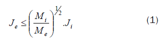
where Mi is the ion mass and Me is the electron mass , Je and Ji are the current densities of the electrons and ions, respectively.
The most common use of electron guns is in cathode ray tubes, which were widely used in computer and television monitors. An electron gun can also be used to ionize particles by adding or removing electrons from an atom. This technology is sometimes used in mass spectrometry in a process called electron ionization to ionize vaporized or gaseous particles. More powerful electron guns are used for welding, metal coating, 3D metal printers, metal powder production and vacuum furnaces.
wide range of the solid surface characteristics, mechanical, chemical, optical, magnetic, electrical incl. superconducting properties can be modified as a result of bombardment with ion and electron beams. Correspondingly, the focus of the electron beam research shifted recently from the fundamental aspects of electron–solid interaction to surface engineering, mainly to nanostructure technology, novel tribiological, corrosion, and optical applications. Ion and electron beam bombardment of a solid target causes a significant transformation to the structure and properties of the bombarded surface [8,9,10]. When a beam of energetic particles enters a solid, several processes are initiated in the area of interaction. The polymer materials are very important in medical applications because it has high biocompatibility, low toxicity and a range of mechanical properties that are similar to those of tissue materials; also it is important material in many industrial applications. Electron and ion beam equipment play a vital role in the semiconductor manufacturing and nanotechnology industries [11,12,13].
A schematic diagram of the high efficiency glow discharge electron source and its associated electrical circuit is shown in Fig.1. This electron source consists of copper Pierce shape anode with a small aperture to confine the discharge and aluminum plane cathode. The anode has an internal diameter equal to 46 mm at the upper side and 20 mm diameter at the lower side and its length is 34 mm. The aluminum cathode has an aperture of diameter 1.5 mm and length equal to 5 mm. Both the Pierce anode and the plane cathode are immersed in an insulator of Bakelite material. A focusing electrode works as an extractor is placed at 4 mm from the cathode exit. The collector (Faraday cup) is situated at a distance of 5 cm from the exit aperture of the cathode and used to measure the output ion beam current. The operating principle of this source is based on the ionization mechanism produced by primary electrons colliding with gas molecules due to a potential difference between the anode and the cathode. The anode is made of copper material which is featured by high ionization coefficient and it looks like a Pierce shape to improve the stability of the discharge. The cathode is made of aluminum which has high secondary emission coefficient.

Figure 1: Schematic diagram of the electron source and its associated electrical circuit.
The working gas is admitted to the source through a hose fixed in a Bakelite flange at the upper side of the anode. A 10 kV power supply is used for initiating the DC discharge (glow discharge) between the anode and the cathode. A complete vacuum system consists of stainless steel silicon oil diffusion pump provided with electrical heater and backed by rotary fore vacuum pump was used. A liquid nitrogen trap is fixed between the electron source chamber and the silicon oil diffusion pump in order to prevent the silicon oil vapour from entering the source chamber. The working gas is transmitted to the source from a gas cylinder through a fine controlled gas admittance needle valve to control and adjust the rate of flow of the gas used.
Experimental results and discussions
In this study, the system is evacuated to about 3x10⁻⁵ mbar to remove the residual gases before the used gas injection in the electron source. The electron source apparatus was cleaned before introducing inside the vacuum system. They were polished, and washed by acetone. The polishing of the electrode parts should remove the irregular parts from their surfaces and the contamination due to the erode materials of the discharge. The absence of the filament in this source means less power consumed than the most other sources of similar size and capability. This affects longer life time of the source than can be expected from most other sources and less sputtering inside the source which decreases the contamination resulting from the material inside the source.
Fig.2 shows the dependence of the electron beam current, Ie on the discharge current, Id for different hydrogen gas pressures. It can be seen that Ie increases by increasing Id and also by decreasing gas pressure. The strongly dependence of the discharge voltage Vd on the gas pressure at different discharge currents is shown in Fig.3. It is clear that the discharge voltage decreases by increasing the hydrogen gas pressure. The electron current depends on the discharge current and the gas pressure.

Figure 2: Relation between the discharge current and the electron beam current at different hydrogen gas pressures.

Figure 3: The discharge voltage as a function of gas pressure at different discharge currents.
Fig. 4 shows the relation between the focusing voltage applied to the focusing electrode and the electron beam current at different hydrogen gas pressures at a fixed distance between the anode and the cathode of 3 mm and discharge current of 0.6 mA. The distance between the cathode exit and the extractor is equal to 4 mm. It is clear from this Figure that, an increase of the focusing voltage applied to the focusing electrode was accompanied by an increase of the electron beam and reaches a maximum value at focusing voltage of – 3 kv with a hydrogen gas pressure of 2x10⁻³ mbar. The maximum electron current for hydrogen gas was found to be 260 μA.

Figure 4: Relation between the focusing voltage applied to the focusing electrode and the electron beam current at different hydrogen gas pressures.
Fig. 5 shows the relation between the focusing voltage applied to the focusing electrode and the electron beam current at different argon gas pressures at a fixed distance between the anode and the cathode of 3 mm and discharge current of 0.6 mA. It is clear from this Figure that, an increase of the focusing voltage applied to the focusing electrode was accompanied by an increase of the electron beam current and reaches a maximum value at focusing voltage of – 2 kv with argon gas pressure of 1.5x10⁻³ mbar. The maximum electron current for argon gas was found to be 175 μA.

Figure 5: Relation between the focusing voltage applied to the focusing electrode and the electron beam current at different argon gas pressures.
Fig. 6 shows the relation between the focusing voltage applied to the focusing electrode and the electron beam current at different air gas pressures at a fixed distance between the anode and the cathode of 3 mm and discharge current of 0.6 mA. It is clear from this Figure that, an increase of the focusing voltage applied to the focusing electrode was accompanied by an increase of the electron beam current and reaches a maximum value at focusing voltage of – 3 kv with air gas pressure of 5x10⁻⁴ mbar. The maximum electron current for air gas was found to be 106 μA, whereas the minimum electron current was found to be 15 μA, at air gas pressure of 1.1x10⁻³ mbar and focusing voltage applied to the focusing electrode of -1.5 kV.

Figure 6: Relation between the focusing voltage applied to the focusing electrode and the electron beam current at different air gas pressures.
Fig. 7 shows the relation between the focusing voltage applied to the focusing electrode and electron beam current with different discharge currents of 0.2, 0.4 and 0.6 mA at hydrogen gas pressure P= 2x10⁻³ mbar and different discharge currents of 0.2, 0.4 and 0.6 mA. It was found that, an increase of the focusing voltage applied to the focusing electrode was accompanied by an increase of the electron current with a higher discharge current of 0.6 mA. The highest electron current was 260 μA, at focusing voltage of – 3 kv.

Figure 7: Relation between the focusing voltage applied to the focusing electrode and electron beam current with different discharge current at hydrogen gas pressure P= 2x10⁻³ mbar.
Fig. 8 shows the relation between the focusing voltage and electron beam current with different discharge currents of 0.2, 0.4 and 0.6 mA, respectively at argon gas pressure P= 2x10⁻³ mbar. It was found that, an increase of the focusing voltage was accompanied by an increase of the electron current at discharge current of 0.6 mA. The highest electron current was 215 μA, at focusing voltage of – 3 kv.

Figure 8: Relation between the focusing voltage applied to the focusing electrode and electron beam current with different discharge current at argon gas pressure P= 2x10⁻³ mbar.
Fig. 9 shows the relation between the focusing voltage and electron beam current with different discharge currents of 0.2, 0.4 and 0.6 mA, respectively at air gas pressure P= 1.1x10⁻³ mbar. It was found that, an increase of the focusing voltage applied to the focusing electrode was accompanied by an increase of the electron current with a higher discharge current of 0.6 mA. The highest electron current was 215 μA, at focusing voltage of – 1.8 kV while the lowest one was found of 18 μA at focusing voltage of – 1.4 kV.

Figure 9: Relation between the focusing voltage applied to the focusing electrode and electron beam current with different discharge current at air gas pressure P= 1.1x10⁻³ mbar.
Fig. 10 shows the influence of the focusing voltage applied to the focusing electrode on the electron current with different gases at discharge current of 0.4 mA and gas pressure of 2x10⁻³ mbar. It was concluded from this Figure that the produced electron current using hydrogen gas was found to be the maximum one and its value reaches 140 μA at focusing voltage of – 1.8 kV while the lowest electron current was found to be 12 μA using nitrogen gas at focusing voltage of – 1.6 kV. Roughly speaking about cathode fall of potential is the product of two functions, the ionization in the gas and the secondary emission at the cathode. Argon and nitrogen gases show large ionization coefficients.

Figure 10: Influence of the focusing voltage applied to the focusing electrode on the electron current with different gases at discharge current of 0.4 mA and gas pressure of 2x10⁻³ mbar.
Glow discharge electron gun applications
The direct current glow discharge electron gun (DCES) is used as a preparation tool of the surface of polyethylene terephthalate PET polymer substrate to be ready for coating or thin film deposition. Also, PVA sample was treated by this electron source and showing a promising results where, argon ion beam has used for this purpose.
Fig.11 shows the influence of the FTIR on the PET sample before and after irradiation with different gases. It is clear from this Fig. , the PET sample irradiated with nitrogen gas is higher than that irradiated with hydrogen one. FTIR spectra show that, there is no change in the overall structure of the polymer but a minor change in intensity of the crystalline band was observed. This perhaps occurs due to the partial increase of the amorphous, where this might be due to the break of few bonds in the structure as well as enhancement of few functional groups. The pristine PET is transparent and its surface is smooth.

Figure 11: FTIR of PET before and after irradiation.
Fig.12 shows the effect of FTIR on the PVA sample before and after irradiation using argon gas. In this case, the sample irradiated with argon gas has a higher transmittance than one without irradiated.

Figure 12: FTIR of PVA before and after irradiation.
The operating parameters for the direct current glow discharge electron gun (DCEG) have been obtained and used for some applications. The best working conditions were found at a gap distance between the anode and the cathode of 3 mm and the distance between the cathode exit and the extractor equals 4 mm. The discharge pressure was found to be in the range of 10-4 mbar and the discharge current of 0.6 mA.
The direct current glow discharge electron gun was used as a preparation tool of the surface of polyethylene terephthalate PET polymer substrate to be ready for coating or thin film deposition, also, PVA sample was treated by this electron source and showing a promising results where, argon electron beam has used for this purpose.
FTIR spectra show that, there is no change in the overall structure of the polymer but a minor change in intensity of the crystalline band was observed. This perhaps occurs due to the partial increase of the amorphous, where this might be due to the break of few bonds in the structure as well as enhancement of few functional groups.